26
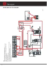
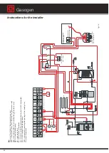
Instructions for the installer
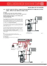
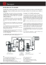
KKP
VE
MKP
IR
Tc
PR
B
AB
UV
A
B
AB
VM
A
M
M
15
17
19
21
23
27
30
16
18
20
22
24
28
31
29
32
PE
BV
AG
W
RAB
L
1
L
1
L
1
L
1
L
1
NN
L
1
NN
1
1
1
1
1
1
1
GM
MKP
33
34
L
1
L
1
1
TAMB
35
38
36
39
37
40
L
1
L
1
N
1
1
KKP
MAXP
PE
BS
SK
25
26
L
1
1
1
41
42
L
1
46
47
TKS
1
1
TR
48
49
1
TC
50
51
43
44
45
L
1
1
NETZ
N
N
L
1
L
1
VENTILAT
ORE
1
C
1
TKS
M
27
27
28
28
29
29
-
-
-
-
30
3334
35
-
-
5051-
C
1
TA
33
34
35
--
ALIMENTAZIONE
2
3
0
V~5
0H
z
C
1
2
30
9
6
3
A1
A2
RELÉ
A
3VIE
8
5
2
7
4
1
L1
N
20
24
N
L1
T1
T2
S3
B4
ALLA
PRESA
A
7
POLI
DEL
BRUCIA
T
ORE
L1
N
P
ANNELLO
CALD
AIA
A
GASOLIO/GAS
Alimentazione
pompa
principale
20
24
30
5051-
VENTILAT
ORE
2
M
27
28
29
--
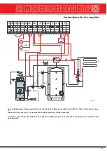
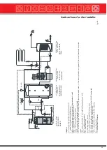
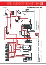
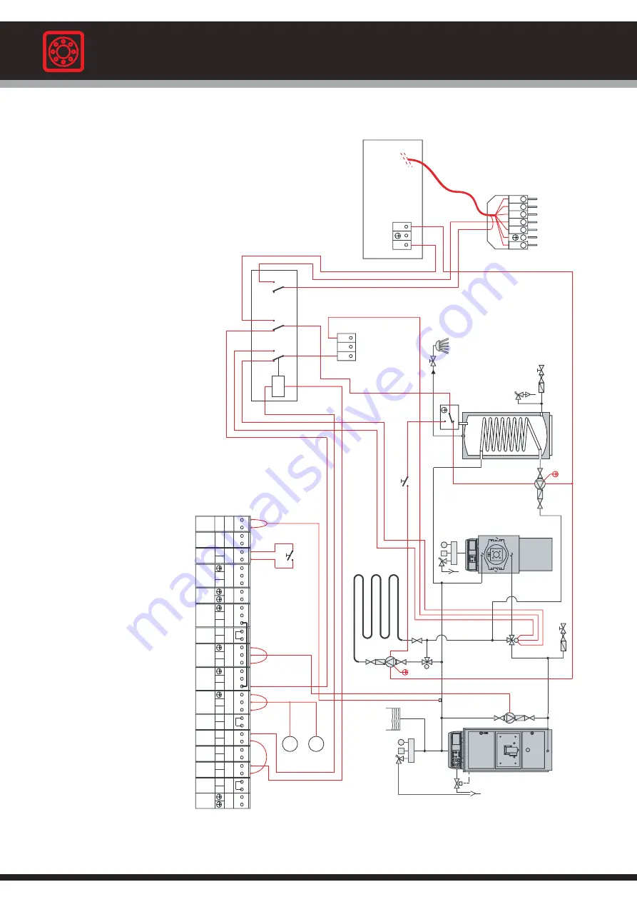
fig.
28
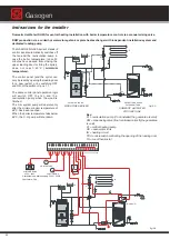
Ke
y
:
Tc
=
w
ood
fired
boiler’
s
flo
w
temper
ature
s
ensor
KKP
=
recirculation
pump
(if
not
installed
the
guar
antee
is
v
oid)
VM
=
z
one
mixing
v
alv
e
(if
not
installed
the
guar
antee
is
v
oid)
MKP
=
c
entr
a
l
heating
pump
VE
=
open
w
a
ter
tank
IR
=
c
entr
a
l
heating
installation
PS
=
D
.H.W
.
recirculation
pump
(controlled
b
y
the
D
.H.W
.
ther
mostat)
PR
=
D
.H.W
.
s
tor
age
tank
loading
pump
TKS
=
micros
witch
controlling
the
opening
of
the
loading
door
T
A
=
room
ther
mostat
Gasogen
Summary of Contents for Gasogen
Page 1: ...Wood Fired Boiler Gasogen 29 93kW Installation and Servicing Manual ...
Page 66: ...Gasogen notes ...
Page 67: ...notes ...

