29
Instructions for the installer
C
1
TA
PMV1
A
B
AB
VE
RMV
SVA
A
B
AB
Tr
Tc
KKP
KRF
B
AB
VM
A
M
MKP
IR
15
17
19
21
23
27
30
16
18
20
22
24
28
31
29
32
PE
BV AGW
RAB
L
1
L
1
L
1
L
1
L
1
N
N
L
1
N
N
1
1
1
1
1
1
1
GM MKP
33 34
L
1
L
1
1
TAMB
35
38
36
39
37
40
L
1
L
1
N
1
1
KKP
MAXP
PE
BS
SK
25 26
L
1
1
1
41 42
L
1
46 47
TKS
1
1
TR
48 49
1
TC
50 51
43 44 45
L
1
1
NETZ
N
N L
1
L
1
C
1
TKS
VENTILATORE 1
M
27
27
28
28
29
29
-
-
-
-
33
34
35
--
50
51-
48
49-
31
24
TT (50-55°C)
C
2
1
24
31
32
30
30
48
49-
50
51-
VENTILATORE 2
M
27 28 29
-
-
fig. 30
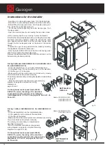
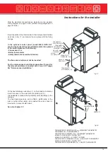
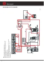
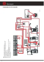
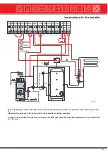
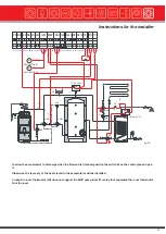
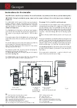
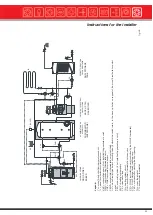
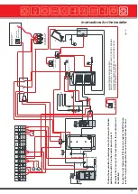
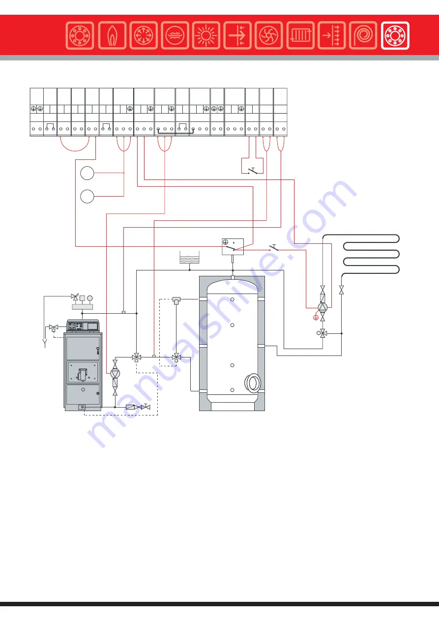
To permit drainage of the accumulator when the firewood is finished, position the switch 23 of the control panel in pos.
II.
Otherwise, the recovery of the heat stored in the accumulator will be prevented.
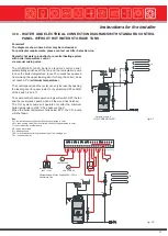
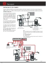
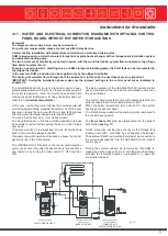
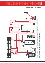
In case the room thermostat (TA) does not support the MKP pump load, fit a relay that separates the room thermostat
from the load.
Summary of Contents for Gasogen
Page 1: ...Wood Fired Boiler Gasogen 29 93kW Installation and Servicing Manual ...
Page 66: ...Gasogen notes ...
Page 67: ...notes ...

