49
Instructions for the installer
5.4 - FUNCTIONAL DESCRIPTION OF OPTIONAL CONTROL PANEL
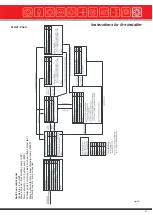
(see flow-chart on page 47)
5.4.1 - IGNITION (see Step 0, Step 1 page 47)
The main switch (pos. 11), the C.H. pump switch (pos. 13) and the fan switch (pos. 12) are all positioned differently to “0”; t he
switch (pos. 11) is illuminated and the control panel board is ON.
The upper loading door is open: the opening of the door causes the fan to switch OFF (Step 1).
The boiler temperature is below the minimum set temperature of about 65°C.
If the installation is equipped with the accumulator foreseen by the Standard EN 303-5, the return thermostatic valve is closed
(see diagrams on pages 28, 30, 32, 35 and 38).
The opening of the loading door activates a control timer (Timer 1) via the microswitch (TKS): the default value of the Timer 1 is
30 minutes and can be increased during the installation stage of an additional 30 minutes.
If the boiler does not reach the minimum temperature (about 65°C) within the foreseen time Timer 1)), the fan and the recircula tion
pump will be switched OFF; in the meantime the back-up boiler’s burner will be activated automatically if the burner switch (po s.
23) is in position “II”
The opening and the closing of the loading door will reset the Timer 1, energizing the
fan and the recirculation pump again.
On the contrary, if the minimum set temperature (higher than 65°C) is reached within the control time (Timer 1), the logical
control will position itself into “normal operation” (Step 3).
5.4.2 - NORMAL BOILER OPERATION (see Step 3, page 47)
The microprocessor’s logical control determines the difference between the boiler temperature (Tc) and the C.H. return temperature
(Tr) and therefore the two following situations can occur:
A - If the difference between the boiler flow temperature (Tc) and return temperature (Tr) is inferior to 6 °C (factory settin g) the
time of Timer 2 is increased; if this one reaches 10 minutes, then the recirculation pump (KKP) and the fan GM are switched OFF.
B - If the difference between the boiler flow temperature (Tc) and return temperature (Tr) is higher than 6 °C (factory setting ) the
Timer 2 is reset to zero and the recirculation pump (KKP) is switched ON.
The above points A and B make up the heat storage tank’s loading strategy, if present (see on page 27).
In general, the opening and closing of the wood loading door, resets the logical control, activating the fan and the recirculat ion
pump again.
In any case the ON and OFF fan function is mainly controlled by the confrontation of the boiler flow temperature (Tc) and the
temperature set by the user via the knob pos. 32.
5.4.3 - NO WOOD (see Step 4, page 47)
The opening of the loading door activates the control timer (Timer 1) via the microswitch (TKS): the default value of the Timer 1
is 30 minutes and can be increased by an additional 30 minutes during the installation stage.
If the boiler does not reach the minimum temperature (about 65°C) within the foreseen time (Timer 1), due to no wood, the fan
and the recirculation pump will be switched OFF; in the mean time the back up boiler’s burner, if the burner switch (pos. 23) i s in
position “II”, will be automatically activated. The opening and the closing of the loading door will reset the Timer 1,
switching ON again the fan and the recirculation pump.
On the contrary, if the minimum set temperature (higher than 65°C) is reached within the control time (Timer 1), the logical
control will return to “normal boiler operation” (Step 3).
Summary of Contents for Gasogen
Page 1: ...Wood Fired Boiler Gasogen 29 93kW Installation and Servicing Manual ...
Page 66: ...Gasogen notes ...
Page 67: ...notes ...

