background image

50

Instructions for the installer

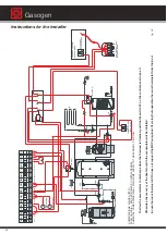
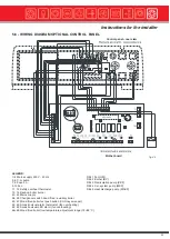
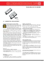
5.4.4 - OIL/GAS BOILER OPERATION (see Step 4, Step 6, page 47)

In installations with a back up oil/gas boiler (hydraulically connected in parallel), the burner is switched ON via the potenti al free
contact BV, if this has been integrated in the burner’s electrical wiring by the installer; in paragraph 3.11 an auxiliary circ uit
diagram is proposed for controlling: - the C.H. pump, controlled by the back-up boiler’s control panel, - the diverting valve, which
allows the water flow to be diverted from the wood fired boiler to the auxiliary one – the back up boiler’s (oil/gas) burner.
In case there is no wood, the back-up boiler is automatically fired according to the steps seen in the previous paragraph.
On the contrary, if the user needs to operate the back- up boiler without waiting the time foreseen by the Timer 1, he only nee ds
to press the keys 22 and 23 respectively in position “I” and “II”.

5.4.5 - DOMESTIC HOT WATER PRODUCTION
Summer mode for only D.H.W, production is not advisable and could, if not controlled properly, cause the intervention
of the safety overheat thermostat (see paragraph 6.11).

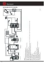
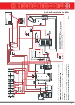
In case the user needs to produce D.H.W, to create these installation systems it is necessary to refer to the principle scheme s
shown on pages 30, 35 and 38.
When designing the system for installing the wood fired boiler and the back up boiler, the engineer has to take into considerat ion
the increase in output necessary for D.H.W. production; normally, in fact, D.H.W. production has priority over the request for heat
and therefore the sizing of the D.H.W. storage tank volume has to be customized to the user’s needs and at the same time it has
to be calculated when dimensioning the boiler in order to avoid long waiting times for the changeover from D.H.W. mode to CH
mode.

As far as D.H.W. production is concerned, the electrical connection to the control panel is described in the WATER AND
ELECTRICAL CONNECTION DIAGRAMS in paragraphs 3.11 and 3.12.

Gasogen

Summary of Contents for Gasogen

Page 1: ...Wood Fired Boiler Gasogen 29 93kW Installation and Servicing Manual ...

Page 2: ...lue outlet connection 40 3 14 Filling the system 41 4 5ELECTRICAL CONNECTIONS 42 4 1 Standard control panel 43 5 1 Optional control panel 45 5 2 Functional wiring diagram Flow chart 46 5 3 Loads and sensors connection diagram 48 5 4 Functional description of optional control panel 49 5 4 1 Ignition 49 5 4 2 Normal boiler operation 49 5 4 3 No wood 49 5 4 4 Oil gas boiler operation 50 5 4 5 Domesti...

Page 3: ... check the state of wear of the anode 1 4 INFORMATIONTO BE HANDED OVERTOTHE USER OR PERSON IN CHARGE OFTHE APPLIANCE The user or the person in charge has to instructed on the use and operation of his heating system in particular Hand over these instructions to the end user or person in charge of the appliance together with any other litera ture regarding this appliance placed inside the envelope c...

Page 4: ...ise the safe operation of the appliance and could cause injury to persons animals or damage to property for which shall not be held liable Automatic Heating Modifications to parts connected to the appliance Do not carry out any modifications to the following parts the boiler to the gas air water supply pipes and electrical current to the flue pipe safety relief valve and to the central heating s d...

Page 5: ...bstruct the intake outlet terminal ducts In the event of failure and or faulty functioning of the appliance switch off the boiler Do not attempt to make any repairs contact qualified technicians Any repairs must be carried out by Automatic heating authorized technicians and using only original spare parts Non observance of the above requirement may jeopardize the safety of the appliance To guarant...

Page 6: ...h side inspection doors and ash removal Flue evacuation via a pressure blower Patented thermostatic valves system Safety heat exchanger Insulated boiler body with 60 mm thickness mineral wool mattress Powder painted steel casing Recirculation pump kit optional Recirculation pump kit for buffer tank optional provided the standard control panel is replaced by the model code 23557 Standard control pa...

Page 7: ...to 15 K Delta T MODELS GASOGEN G3 25 2S GASOGEN G3 40 2S GASOGEN G3 50 2S kW 15 23 29 AVERAGE OUTPUT MINIMUM OUTPUT MAXIMUM USEFUL OUTPUT kW 26 37 47 kW 29 47 58 MAXIMUM OUPUT kW 34 55 69 DIMENSIONS A B C D E F G 560 700 655 700 655 900 1225 1355 190 315 190 315 245 1030 1355 190 315 245 245 1140 1140 mm mm mm mm mm mm mm CONNECTIONS T1 T2 T3 T4 T5 T6 T7 T8 UNI ISO 7 1 Ø mm UNI ISO 7 1 Rp 1 150 R ...

Page 8: ...cessary that the flame in its convective motion does not meet another fuel in addition to the one which it has generated it As in residential heating the fuel is in form of wood logs which are loaded from the top the flame has to go in the opposite way i e downwards Natural draught is a very variable source of depression according to the type of chimney on the weather conditions on the type of fue...

Page 9: ...ulphur concentrations are not very high it is important to obtain very low smoke temperatures in order to increase the water efficiency To obtain this Automatic Heating has opted for an exchange surface with dry smoke passes fig 4 which have already been extensively tested in oil fired boilers working at low water temperature thus permitting low smoke temperatures without danger of condensate form...

Page 10: ...id wood Nevertheless all these expedients do not impede the formation of condensate in the chimney Therefore we suggest when building the chimney to use air tight components to avoid the condensate damaging the building structure COMBUSTION CHAMBER 5 The combustion is optimised by increasing the flame temperature and producing a strong turbulence in the bottom chamber For this reason the flame in ...

Page 11: ...th the wood storage completely full of humid wood Nevertheless all these expedients do not impede the formation of condensate in the chimney Therefore we suggest when building the chimney to use air tight components to avoid the condensate damaging the building structure ...

Page 12: ...installing the boiler the following points have to be carried out by a professionally qualified person a The whole system should be thoroughly flushed in order to remove any residual dirt or grime which could compromise correct boiler operation b Check that the chimney flue pipe has an adequate draught does not have any constrictions and that no other appliance s flue outlets have been fitted unle...

Page 13: ...tions for the installer 3 2 INSTALLATION CODES OF PRACTICE The GASOGEN G3 2S is a boiler foreseen for operation with firewood The appliance must be installed in compliance with all applicable laws and regulations ...

Page 14: ...to property deriving from not having respected the above mentioned recommendations Packages description 1 Boiler body 2 Package containing the casing and boiler insulation 3 Package containing the control panel 4 Package containing insulation fixing kit fan air manifold group smoke chamber inspection doors handles flame sight mirror In the documents placed in the fire box you will find User s inst...

Page 15: ... so as to reduce possible vibrations and noise An adequate clearing must be left behind the boiler for servicing INSTALLATION IN BOILER ROOM Note The minimum clearances indicated in figure 9 are compulsory only for boilers with an output higher than 35 kW fig 9 3 6 BOILER SYSTEM CONNECTION Warning Make sure the connection of the pipelines is free of mechanical stresses in order to avoid pressure l...

Page 16: ...Warning In absence of this precautionary measure the eventual intervention of the heat discharge valve could cause damages to people animals or property The manufacturer shall not be held liable for any such injury and or damage 3 8 RECIRCULATION PUMP For correct boiler operation it is necessary to install a recirculation pump in the boiler The recirculation pump supplied as an optional kit in two...

Page 17: ...e plastic strap already inserted steady proceed with the other end by bending towards the inside the plastic pin as shown in detail 2 L Pull the ends of the strap as shown in details 3 4 till it adheres completely to the glass wool covering the boiler body Please do not pull the strap too much as too much compression of the rock wool insulation will cause an uniformed insulation fig 11 fig 12 fig ...

Page 18: ...diate door Fit the gasket pos 4 and the plate pos 5 to the manifold Fit the fan pos 7 to the plate Make sure the air non return plate is not blocked by moving the air manifold s external lever manually The primary and secondary air draught adjustment is described on page 57 Wire the electrical connections see general wiring diagram on page 44 and practical wiring diagrams on page 21 22 On the opti...

Page 19: ...cted with it see 5 5 7 page 52 Return sensor installation fig 18 Wire the electrical connections as indicated on the general wiring diagram on page 44 and practical wiring diagrams on page 21 22 Fit the heat discharge valve pos 1 on the safety coil inlet and insert its sensor in the relevant bulb holder pos 2 It is advisable to redirect the heat safety valve discharge to the sewage The heat discha...

Page 20: ...ge 27 NOTE For correct control of the storage tank in addition to fitting the recirculation kit foreseen for this purpose the optional control panel code 23577 must be fitted To ensure correct operation of the GASOGEN G3 2S boilers when a storage tank is used it is indispensable to install the return sensor Tr as shown in the diagrams in figs 29 31 33 35 and 37 Automatic Heating has developed a RE...

Page 21: ...ere below may be customized For particular requirements please contact our After Sales Service Domestic hot water production for a central heating system with boiler temperature control via manual mixing valve The GASOGEN G3 2S boiler s standard control panel automatically switches off the fan and the recirculation pump in case the boiler temperature once 30 minutes have passed from closing the up...

Page 22: ...an and the recirculation pump in case the boiler temperature once 30 minutes have passed from closing the upper loading door for firing the boiler does not reach 65 C minimum temperature The control panel and the cycle can only be reset by opening the loading door for a new restart or by switching OFF and ON of the switch in pos 11 The same control panel operation logic will switch OFF the fan and...

Page 23: ...ystem and dedicated loading pump The two boilers are hydraulically connected in series with the wood fired boiler system flow connected to the oil gas fired boiler s system return There is no need to install a diverting valve or DHW storage tank loading pump the DHW tank can be incorporated in the oil gas fired boiler In the summer DHW production can be supplied only by the oil gas fired boiler Th...

Page 24: ... BRUCIATORE L1 N PANNELLO CALD AIA A GASOLIO GAS Alimentazione pompa principale C 1 2 50 51 33 34 35 C 1 TA 11 14 12 A1 A2 21 24 22 20 24 30 RELÉ A 2VIE FINDER TYPE 95 05 230V VENTILATORE 2 M 27 28 29 fig 26 Key Tc wood fired boiler s flow temperature sensor KKP recirculation pump if not installed the guarantee is void VM zone mixing valve if not installed the guarantee is void MKP central heating...

Page 25: ... boiler in this case will be excluded and it will be possible to restart it after opening the door in order to load new wood If the burner switch 23 is always kept on pos 0 the auxiliary boiler s burner will be always excluded Obviously to permit operation of the back up boiler the control panel must be in the ON position The GASOGEN G3 2S boiler s control panel and operation cycle can be reset on...

Page 26: ... C 1 2 30 9 6 3 A1 A2 RELÉ A 3VIE 8 5 2 7 4 1 L1 N 20 24 N L1 T1T2 S3 B4 ALLA PRESA A 7 POLI DEL BRUCIATORE L1 N PANNELLO CALD AIA A GASOLIO GAS Alimentazione pompa principale 20 24 30 50 51 VENTILATORE 2 M 27 28 29 fig 28 Key Tc wood fired boiler s flow temperature sensor KKP recirculation pump if not installed the guarantee is void VM zone mixing valve if not installed the guarantee is void MKP ...

Page 27: ...onomia h Qmin potenza utile minimale kW where V accumulator buffer tank volume litres Qn nominal heat output kW T autonomy h Qmin minimum heat output kW The boiler s nominal heat output Qn must be equal to the building s heat losses Some of the boiler models are equipped with automatic or manual systems for the reduction of the nominal heat output in case of reduced load the minimum heat output in...

Page 28: ...seasonal efficiency from the GASOGEN G3 2S boiler and a better management of the heating system as well as a longer life span of the boiler by reducing the temperature peaks caused by inconstant drawing offs from the heating system itself Moreover the heat accumulator makes you save a lot on your gas bill This type of installation is particularly effective during the mid seasons since it avoids ha...

Page 29: ...R 48 49 1 TC 50 51 43 44 45 L1 1 NETZ N N L1L1 C 1 TKS VENTILATORE 1 M 27 27 28 28 29 29 33 34 35 50 51 48 49 31 24 TT 50 55 C C 2 1 24 31 32 30 30 48 49 50 51 VENTILATORE 2 M 27 28 29 fig 30 To permit drainage of the accumulator when the firewood is finished position the switch 23 of the control panel in pos II Otherwise the recovery of the heat stored in the accumulator will be prevented In case...

Page 30: ...lator in the heating system see dimensioning on page 27 enables you to obtain a high seasonal efficiency from the GASOGEN G3 2S boiler and a better management of the heating system as well as a longer life span of the boiler by reducing the temperature peaks caused by inconstant drawing offs from the heating system itself Moreover the accumulator makes you save a lot on your gas bill This type of ...

Page 31: ...29 29 33 34 35 50 51 48 49 30 31 19 PMV1 A B AB VE RMV SVA A B AB Tr Tc KKP KRF B AB VM A M MKP IR TT 50 55 C C 2 1 24 C 1 TA 31 PR C 1 2 TB 45 60 C 31 50 51 48 49 VENTILATORE 2 M 27 28 29 32 30 32 fig 32 To allow the accumulator to discharge when the firewood is finished position the switch 23 on the control panel in pos II Otherwise the recovery of the heat stored in the accumulator will be inhi...

Page 32: ...see installation mode in paragraph 5 5 7 The jumper 71 72 on the PCB must be removed The introduction of an accumulator in the heating system see dimensioning sizing on page 27 enables you to obtain a high seasonal efficiency from the GASOGEN G3 2S boiler and a better management of the heating system as well as a longer life span of the boiler by reducing the temperature peaks caused by inconstant...

Page 33: ...A A B AB Tr Tc KKP KRF B B AB AB UV VM A A M M MKP IR N L1 T1T2 S3 B4 L1 N PANNELLO CALDAIA A GASOLIO GAS Alimentazione pompa principale TT 50 55 C C 2 1 24 C 1 TA 31 9 6 3 A1 A2 RELÉ A 3 VIE 8 5 2 7 4 1 20 ALIMENTAZIONE 230V 50 Hz L1 N 50 51 48 49 VENTILATORE 2 M 27 28 29 32 fig 34 To allow the accumulator to discharge when the firewood is finished position the switch 23 on the control panel in p...

Page 34: ...iciency from the GASOGEN G3 2S boiler and a better management of the heating system as well as a longer life span of the boiler by reducing the temperature peaks caused by inconstant drawing offs from the heating system itself Moreover the accumulator makes you save a lot on your gas bill This type of installation is particularly effective during the mid seasons since it avoids having to use reduc...

Page 35: ...alve sensor PMV1 accumulator thermostatic valve optional UV wood fired oil gas boiler s diverting valve it directs the tank s return to the back up boiler on request of the wood fi red boiler s control panel VM zone mixing valve if not installed the guarantee is void MKP heating system pump VE open water tank IR heating system circuit SVA accumulator thermostatic valve sensor PS D H W recirculatio...

Page 36: ...V 50 Hz L1 N 50 51 48 49 33 34 35 TT 50 55 C C 2 1 24 N L1 T1T2 S3 B4 ALLA PRESA A 7 POLI DEL BRUCIATORE L1 N PANNELLO CALDAIA A GASOLIO GAS Alimentazione pompa principale C 1 2 TB 45 60 C 3 0 31 C 1 TA 31 VENTILATORE 2 M 27 28 29 32 32 fig 36 To allow the accumulator to discharge when the firewood is finished position the switch 23 on the control panel in pos II Otherwise the recovery of the heat...

Page 37: ...per 71 72 on the PCB must be removed The introduction of an accumulator in the heating system see sizing on page 27 enables you to obtain a high seasonal efficiency from the GASOGEN G3 2S boiler and a better management of the heating system as well as a longer life span of the boiler by reducing the temperature peaks caused by inconstant drawing offs from the heating system itself Moreover the acc...

Page 38: ...accumulator thermostatic valve optional UV wood fired oil gas boiler s diverting valve it directs the tank s return to the back up boiler on request of the wood fi red boiler s control panel VM zone mixing valve if not installed the guarantee is void MKP heating system pump VE open water tank VE1 closed water tank IR heating system circuit CS solar collector RS Solar collector controller SP Solar ...

Page 39: ... ALIMENTAZIONE 230V 50 Hz L1 N L1 N ALIMENTAZIONE 230V 50 Hz 9 6 3 A1 A2 RELÉ A 3 VIE 8 5 2 7 4 1 20 N L1 T1T2 S3 B4 ALLA PRESA A 7 POLI DEL BRUCIATORE L1 N PANNELLO CALD AIA A GASOLIO GAS Alimentazione pompa principale C 1 TA 31 31 VENTILATORE 2 M 27 28 29 32 32 fig 38 To allow the accumulator to discharge when the firewood is finished position the switch 23 on the control panel in pos II Otherwi...

Page 40: ...ints to avoid that flue condensate leave the walls dirty due to permeation The entrance to the chimney should be at an angle of 45 At the base of the chimney a flue inspection opening has to be made It is advisable to insulate the boiler pipe connection to the chimney in order to reduce the heat losses and noise 1 Boiler 2 Flue outlet connection 3 Ashes collecting chamber 4 Chimney 5 External flue...

Page 41: ... once again through the radiator s air vents check all the connections for soundness after having fired the boiler for the first time and the system has reached the correct temperature arrest the pump and repeat the air bleeding operations let the system cool down and if necessary re establish the water pressure to 1 bar this is valid only for installations equipped with a closed expansion vessel ...

Page 42: ...ectric connections for the standard control panel board are shown in page 46 and for the optional control panel board in the section Loads and Sensors connection paragraph 5 3 page 48 A mains supply of 230 V 50 Hz is required The wiring to the boiler must be in accordance with the current CEI regulations DANGER The electrical connections must be carried out only by a qualified engineer Before carr...

Page 43: ...mp running until this temperature is reached If the boiler does not reach the 65 C in the set time the temporized relay stops the fan This can be due to the boiler not firing or due to an insufficient load of the firewood To avoid this inconvenience it is possible to increase the temporized relay s intervention time this operation has to be done only by trained personnel or more firewood has to be...

Page 44: ...l F1 General fuse max 4A IG Mains switch with warning light Ipi C H pump switch Iv Fan switch LL Power ON lamp Pi C H system pump Pr Recirculation pump Rt Temporized relay R1 Relay Te Working thermostat 75 C 85 C TKS By pass shaft microswitch Tmax Limit thermostat 90 C Ts Safety overheat thermostat 100 C Tsc Minimum thermostat for wood fired boiler 65 C V Fan s 34 reference to front view facia pan...

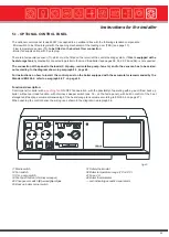
Page 45: ... 38 is not supplied The connection of the panel to the loads C H pump recirculation pump fan etc and to the sensors has to be carried out according to the diagram shown in paragraph 5 3 page 48 For instructions on how to install the control panel on the boiler equipped with the accumulator recommended by the Standard EN 303 5 refer to paragraph 5 5 7 on page 52 Functional description Control panel...

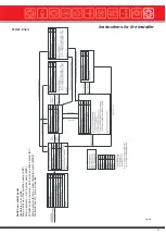
Page 46: ...the fan s ignition when the loading door is opened If the fan works by pushing as in the case of the GASOGEN G3 2S boiler make sure that the jumper on the PINS 54 55 is OFF IL 1 The status of the logical function which allows the transfer from the wood fired to the oil gas fired one is indicated in th e Flow Chart with LG and associated to the switch in pos 22 on the facia panel Position 0 LG 1 Po...

Page 47: ...itch on control panel Ventilatore Fan GM Pompa ricircolo Recirculation pump KKP Pompa impianto C H System pump MKP Contatto pulito bruciatore Burner tension free contact BV Pompa scarico termico Heat discharge pump MAXP Ponticello inserito Jumper inserted ...

Page 48: ...r N GM 29 Fan motor GM 30 C H pump L1 MKP 31 C H Pump N MKP 32 C H Pump MKP 33 Recirculation pump L1 KKP 34 Recirculation pump N KKP 35 Recirculation pump KKP 36 Room thermostat L1 TAMB 37 Room thermostat L1 TAMB 38 Heat discharge pump L1 MAXP 39 Heat discharge pump N MAXP 40 Heat discharge pump MAXP 41 Earthing PE 42 Earthing PE 43 Phase L1 44 Neutral 45 Earthing PE 46 Limit switch TKS 47 Limit s...

Page 49: ...perature Tc and the C H return temperature Tr and therefore the two following situations can occur A If the difference between the boiler flow temperature Tc and return temperature Tr is inferior to 6 C factory settin g the time of Timer 2 is increased if this one reaches 10 minutes then the recirculation pump KKP and the fan GM are switched OFF B If the difference between the boiler flow temperat...

Page 50: ...tively in position I and II 5 4 5 DOMESTIC HOT WATER PRODUCTION Summer mode for only D H W production is not advisable and could if not controlled properly cause the intervention of the safety overheat thermostat see paragraph 6 11 In case the user needs to produce D H W to create these installation systems it is necessary to refer to the principle scheme s shown on pages 30 35 and 38 When designi...

Page 51: ...nd a back up oil fired boiler a gas fired boiler needs its own chimney it is possible to fit a flue thermostat in the part of the chimney serving only the wood fired boiler connected to the AGW terminals in order to stop the burner firing in case the flue temperature of the wood fired boiler is over 100 C 5 5 3 FAN OVERHEATING PROTECTION SYSTEM In this range of boilers GASOGEN G3 2S this system is...

Page 52: ...ed with the boiler between the pins 69 70 WARNING The installer once the commissioning is finished must remove the a m jumper from the terminals 69 70 in order to restore normal operation the manufacturer declines any responsibility and or additional costs connected if normal boiler operation is not restored 5 5 7 RETURN FLOW SENSOR Tr INSTALLATION The installation of the accumulator foresees the ...

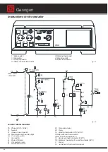
Page 53: ...9 Changeover switch wood fired auxiliary boiler 60 61 Wood fired boiler test push button Chimney sweeper 62 63 Acoustic visual alarm thermostat fan overheating 64 65 Acoustic visual LED alarm fan overheating 66 68 Wood fired boiler flow temperature adjustment range 75 85 C fig 46 Control panel rear view Mother board REL 1 Fan GM REL 2 Burner BV REL 3 Recirculation pump KKP REL 4 C H system pump MK...

Page 54: ...d and that it is connected to the sewage system there are no water leaks all the necessary ventilation conditions and minimum clearance distances are guaranteed for subsequent servicing LIGHTING AND SHUTTING DOWN PROCEDURES For lighting and shutting down the boiler refer to the USER INSTRUCTIONS MANUAL Information to be passed on to the user The user must be instructed on the use and operation of ...

Page 55: ...the boiler s output and therefore to reduce its autonomy Moreover they fall with greater facility in the lower chamber reducing the risk of the formation of bridges The so called bridge is an empty space in the firebox where unburnt wood logs remain In this case the bed of embers is not fed with continuity and the refractory burner s slot is uncovered In these conditions preferential air passages ...

Page 56: ...es Important during boiler operation the bypass must be always perfectly closed The wood has to be of the following length according to the boiler model a 50 cm 1 cm 4cm for the GASOGEN G3 25 2S and GASOGEN G3 40 2S models b 70 cm 1 cm 4 cm for the GASOGEN G3 50 2S and GASOGEN G3 65 2S models c 100 cm 1 cm 4 cm for the GASOGEN G3 80 2S model These dimensions must be absolutely respected In order t...

Page 57: ...e but not a reddish colour P Reasonably open in order to obtain a sufficient gasification Example n 2 Very inflammable wood logs S Completely open P Slightly closed to reduce the gasification but sufficiently open to evacuate the ash that can close the combustion head GENERAL SUGGESTIONS Better performances are obtained after two three days of operation The refractory cement in fact needs to be ba...

Page 58: ...nto contact with relatively cold surfaces with a minimum temperature of about 60 70 C the steam water condensates and in combination with other combustion products originates corrosion phenomena of the metallic parts Every day check if there are signs of smoke condensation black liquid on the floor behind the boiler In this case you must use a wood with a lower moisture content check that the reci...

Page 59: ...he plastic cap If the boiler safety s thermostat has to intervene frequently pos 31 reduce the setting temperature of the working thermostat pos 32 on the control panel If this problem is repeated inform the local After Sales Service 6 11 SUMMER OPERATION Use of the boiler in summer for the production of only domestic hot water is not advised unless you follow these rules meticulously 1 Use very d...

Page 60: ...n unused for long periods see paragraph 6 9 Use thicker wood logs Use up all the wood before loading a new batch Problem The boiler does not reach the requested temperature The flame is small and there is too much air When the fire box is checked a formation of log bridges is found Remedy Check the length of the wood logs see paragraph 6 6 Check how the wood logs are loaded in the fire box see par...

Page 61: ... a new batch Problem The boiler does not reach the requested temperature The flame is small and there is too much air When the fire box is checked a formation of log bridges is found Remedy Check the length of the wood logs see paragraph 6 6 Check how the wood logs are loaded in the fire box see paragraph 6 6 Cut the logs in two parts see paragraph 6 6 Use smaller logs round or square 5 to 7 cm di...

Page 62: ...dicated INSTRUCTIONS FOR INSPECTION AND SERVICING To ensure a long life to all your boiler components and in order not to alter the conditions of the approved product only original Automatic Heating spare parts must be used Before servicing always carry out the following steps Disconnect the mains electricity supply Separate the appliance from the electrical supply by means of a separating device ...

Page 63: ...the chimney or flue outlet system and their accessories switch OFF the boiler and when the work is finished check that they are functioning correctly Do not clean the boiler or its parts with easily inflammable products gasoline alcohol etc Do not leave inflammable products in the room where the boiler is installed Do not clean the boiler room when the boiler is firing At the end of the heating se...

Page 64: ...ke the fan noisy during operation and could reduce the fan s performances Cleaning the primary and secondary air distributor Remove the central wall fig 50 where the air adjustments are placed and clean the inner space carefully from tarry residues dust and wood flakes which have entered through the primary air holes Clean the secondary air passages carefully with a soft brush Gasogen ...

Page 65: ...rity of doors seals Correct operation of the loading door microswitch Cleaning the fan blades Fan noise Cleaning the flue circuit on the rear side of boiler If necessary replace If necessary replace If necessary replace If necessary clean them If necessary adjust it If necessary repair it using the refractory kit see spare parts list If necessary re position it If necessary repair and or replace t...

Page 66: ...Gasogen notes ...

Page 67: ...notes ...

Page 68: ...ting Pty Ltd ABN 90 446 545 923 51 Assembly Tullamarine Vic 3043 Australia PO Box 356 Tullamarine Vic 3043 Australia 61 3 9330 3300 61 3 9310 5655 sales automaticheating com au Telephone Facsimile Email www automaticheating com au ...

Reviews: