1.02
Leveling the Machine
on location is important for the
machine to function properly. The four leveling screws in
the legs are the means of leveling the machine. After
positioning the machine, level machine in front to rear and
right to left directions. After leveling, turn front right (lock
side) leveling screw in about one-half turn to drop this
corner slightly to make the door easier to close and lock.
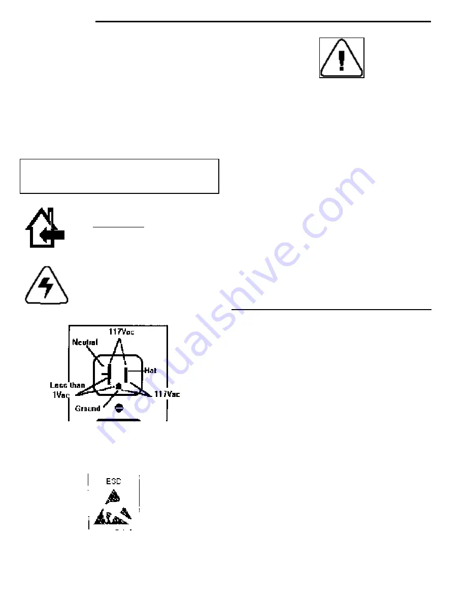
Voltage and Polarity Check.
It is important that this
machine is hooked up to the proper voltage and polarity.
Using a voltmeter, perform the following checks from the
illustration below.
◆
NOTE: It is imperative that the machine is on it’s own
20 AMPERE SERVICE. Only the Control module may be
plugged into the same service.
NOTE: Should the readings be different from above ,
have a certified electrician correct the problem.
For Health reasons it should be noted that cold
(refrigerated) or frozen vending machines are designed
for short term storage of already refrigerated or frozen
product. The definitions for cold and frozen machines are
as follows:
1. Cold is defined as 41°F (5°C) or lower for cold food.
All food in a Refrigerated machine must have a
product expiration date on the package. See your
product suppler for specifics on date codes and
expiration dates.
2. Slack is defined as a frozen machine set below 15°F
(-9°C) or lower for slacking precooked frozen food.
3. Frozen is defined as 0°F (-18°C) or lower for frozen
food. Items used in a frozen machine should have
frozen designated packaging.
When installing a machine, the machine should be
allowed to pull down to operating temperature before
loading product into the machine, approximately 1 hour
for a cold machine and 2 hours for a frozen machine.
See blue page 3.01 for instructions on setting tempera t u r e.
For more information on pull down times and health
control see page 2.03 of the components section of this
manual.
Loading Shelves.
Open door to full open position, push
down on the two plastic lock levers on right and left side
panel by shelf to unlock shelf, holding lever down. Grasp
the shelf, under both front corners, lift front shelf slightly
and pull forward until shelf reaches its stop. The shelves
tilt down (do not drop) to make loading easier. Only one
product shelf should be in the loading position at a time.
When returning a shelf, be sure the shelf is in its full home
or vend position. Begin loading
with the top shelf. Move it to the loading position.The
height spacing for items is greatest in this shelf and the
tallest items should be placed there. Soft items, should
be placed in the lowest shelf, making the drop distance
as short as possible.
installation
CAUTION:
THIS MACHINE IS DESIGNED
FOR INDOOR USAGE ONLY. ANY OTHER
USAGE MAY VOID THE MANUFACTURERS
WARRANTY.
CAUTION:
THE FOLLOWING PROCEDURE
REQUIRES THAT THE MACHINE HAVE
POWER APPLIED AND A POTENTIAL
ELECTRICAL SHOCK HAZARD EXISTS.
Summary of Contents for 310
Page 45: ...section 5 parts This Page Intentionally Left Blank ...
Page 46: ...5 01 310 control module cabinet ...
Page 48: ...5 03 310 control module door ...
Page 50: ...5 05 310 swing panel ...
Page 52: ...5 07 310 board and power box assembly 21 24 ...
Page 54: ...5 09 310 power supply box ...
Page 56: ...5 11 320 inside door ...
Page 58: ...5 13 320 thermal window 4 6 2 8 5 12 10 11 14 1 15 13 7 16 3 17 18 ...
Page 64: ...5 19 320 baffle door assembly 8 7 6 6 4 3 5 2 1 10 9 11 ...
Page 66: ...5 21 320 baffle motor assembly 7 8 9 6 5 20 5 19 12 3 2 1 4 18 17 15 16 14 13 11 10 ...
Page 68: ...5 23 320 refrigeration assembly and components 7 6 5 12 10 13 1 4 3 11 8 ...
Page 72: ...5 27 320 junction box side wall mount 14 21 9 2 4 1 17 7 20 6 3 8 5 19 15 ...
Page 74: ...5 29 320 8 select spiral shelf 18 16 17 10 9 11 16 13 14 12 11 9 10 1 15 8 3 2 7 5 4 6 ...
Page 76: ...5 31 320 conveyor shelf 7 4 5 14 13 17 12 10 8 9 6 11 16 2 16 3 1 15 ...
Page 78: ...5 33 320 conveyor module 1 5 4 6 13 14 16 8 7 11 12 17 3 12 20 9 15 2 8 18 19 10 16 ...
Page 80: ...5 35 310 trim Top Trim or Trim Insert Trim Outside Vertical Trim Lower Horizontal Bottom Trim ...
Page 82: ...5 37 310 panels Lower Panel Upper Panel Top Insert ...
Page 89: ...6 01 trouble shooting chart ...
Page 90: ...6 02 trouble shooting chart ...
Page 91: ...6 03 trouble shooting chart ...
Page 94: ...6 06 electrical connections ...
Page 95: ...6 07 electrical connections P7 Default Refrigeration Jumper HI Refrigerated LO Frozen ...
Page 96: ...notes ...
Page 97: ......
Page 98: ...55 ...
Page 99: ......
Page 100: ...55 ...


