6.04
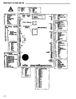
MasterMenu Keypad pinouts
MasterMenu Plug Orientation
Control Board Installation Instructions
(For Lcb part’s 360251 & 360274)
When installing this board into any machine it is necessary that the board be reset to factory defaults.
Instructions to reset the board are as follows:
Install the board into the machine and reconnect all the harnesses and power up the machine.
1.
Open Machine/Tower door.
The display should say Enter for MasterMenu.
2.
Press Enter.
3.
Press the > until the display indicates Security.
4.
Press Enter
5.
The display will indicate Machine ID, press the < one time and the display will indicate Machine Reset - N.
6.
Press the + key the display will indicate Machine Reset machine - Y.
7.
Press the Enter key, The display will indicate Reset - Messages.
8.
Press the + key until the display indicates Reset - All.
9.
Press Enter, the key and the display will indicate Are you Sure - N.
10.
Press the + key and the display will indicate Are you Sure - Y.
11.
Press the Enter key and board will beep and the display will default to Machine Reset - N.
The Board has now been set to factory default.
12.
See quick set up reference page in the Service Manual for Instructions on programing the Control Board.
CAUTION
THE FOLLOWING PROCEDURE REQUIRES THAT PROPER ANTI STATIC
PRECAUTIONS ARE TAKEN OR DAMAGE TO THE BOARD MAY RESULT.
Summary of Contents for 310
Page 45: ...section 5 parts This Page Intentionally Left Blank ...
Page 46: ...5 01 310 control module cabinet ...
Page 48: ...5 03 310 control module door ...
Page 50: ...5 05 310 swing panel ...
Page 52: ...5 07 310 board and power box assembly 21 24 ...
Page 54: ...5 09 310 power supply box ...
Page 56: ...5 11 320 inside door ...
Page 58: ...5 13 320 thermal window 4 6 2 8 5 12 10 11 14 1 15 13 7 16 3 17 18 ...
Page 64: ...5 19 320 baffle door assembly 8 7 6 6 4 3 5 2 1 10 9 11 ...
Page 66: ...5 21 320 baffle motor assembly 7 8 9 6 5 20 5 19 12 3 2 1 4 18 17 15 16 14 13 11 10 ...
Page 68: ...5 23 320 refrigeration assembly and components 7 6 5 12 10 13 1 4 3 11 8 ...
Page 72: ...5 27 320 junction box side wall mount 14 21 9 2 4 1 17 7 20 6 3 8 5 19 15 ...
Page 74: ...5 29 320 8 select spiral shelf 18 16 17 10 9 11 16 13 14 12 11 9 10 1 15 8 3 2 7 5 4 6 ...
Page 76: ...5 31 320 conveyor shelf 7 4 5 14 13 17 12 10 8 9 6 11 16 2 16 3 1 15 ...
Page 78: ...5 33 320 conveyor module 1 5 4 6 13 14 16 8 7 11 12 17 3 12 20 9 15 2 8 18 19 10 16 ...
Page 80: ...5 35 310 trim Top Trim or Trim Insert Trim Outside Vertical Trim Lower Horizontal Bottom Trim ...
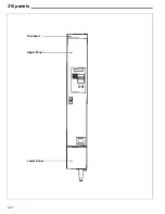
Page 82: ...5 37 310 panels Lower Panel Upper Panel Top Insert ...
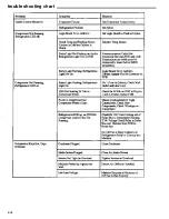
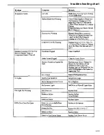
Page 89: ...6 01 trouble shooting chart ...
Page 90: ...6 02 trouble shooting chart ...
Page 91: ...6 03 trouble shooting chart ...
Page 94: ...6 06 electrical connections ...
Page 95: ...6 07 electrical connections P7 Default Refrigeration Jumper HI Refrigerated LO Frozen ...
Page 96: ...notes ...
Page 97: ......
Page 98: ...55 ...
Page 99: ......
Page 100: ...55 ...


