Automatic Systems
PNG38X-A3_1-04-gb-02.doc
10/12/01
p. 17/51
3.4. Electrical connections
•
The electrical connections must be made according to the electrical diagrams 1PNG04.012, 1PNG04.013,
1PNG04.014, and 1PICTO.002 supplied with the equipment (also enclosed to this manual).
•
The PNG38x can also be connected to an IT network.
W
ARNING
:
Make sure that the power supply cables are not live.
3.4.1.
Right or intermediate gate
Master lateral door (
10:1
):
--
Connect the main single-phase power supply to the upper terminals L1 and L2 of the main magneto-
thermal circuit breaker and to the upper terminal PE (earth), located beside the circuit breaker.
--
Route the “passage allowed” control cables in direction A and B and bring them into the PLC
compartment.
--
Route the motor cables to the left gate.
Lateral door (
10:2
):
--
Connect the intergate cable to the connector X6, referring to the proper electrical diagram.
--
Connect the “passage allowed” control cable in direction A and B to the connection block X13.
3.4.2.
Left gate
Lateral door (
10:4
):
--
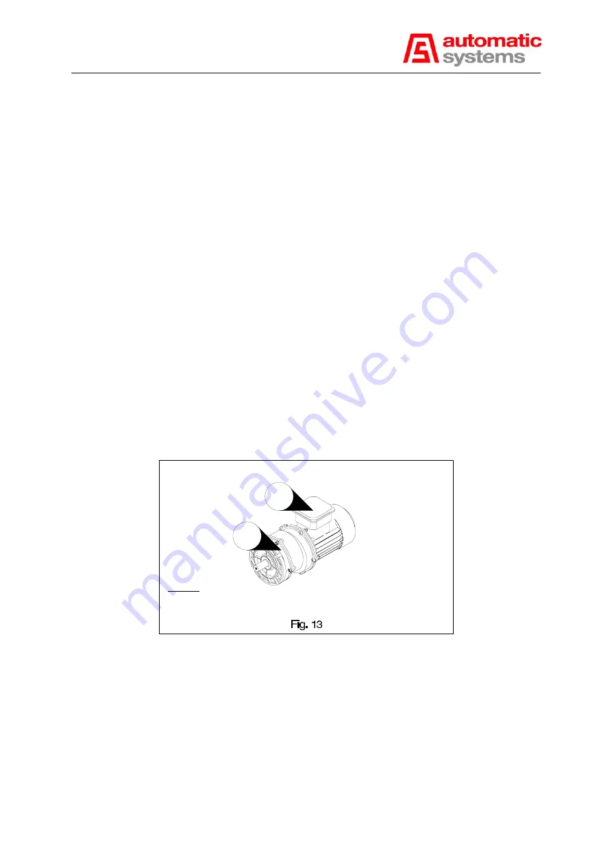
Connect the motor cable directly into the connection box (
13:2
) of the motor, respecting the polarity.
W
ARNING
:
Fix the cable by inserting the earth braid through the grommet.
13:1 Geared motor
13:2 Geared motor connection block
Legend:
13:1
13:2
--
Connect the cable from the connector X6 according to the electrical diagram 1PNG04.013 for an
intermediate gate or 1PNG04.014 for a left gate.


