Automatic Systems
PNG38X-A3_1-04-gb-02.doc
10/12/01
p. 47/51
8. MECHANICAL ADJUSTMENTS AND INTERVENTIONS
WARNING!
REMINDER: Y
OUR AUTOMATIC GATE TYPE
"PNG380/381/382"
COMPRISES A MECHANISM AND VARIOUS ELECTRICAL
COMPONENTS
. A
NY NEGLIGENCE DURING AN INTERVENTION IN THE MACHINE MAY SERIOUSLY ENDANGER YOUR SAFETY
. A
S
SOON AS YOU OPEN THE HOUSING
,
SWITCH OFF THE MAIN MAGNETO
-
THERMAL CIRCUIT BREAKER
(
2:1
)
OF THE MASTER GATE
,
WHICH IS LOCATED BEHIND THE LATERAL POLYESTER DOOR
(
10:1
). B
E CAREFUL IN HANDLING ANY INTERNAL ELEMENT WHICH
MIGHT BE UNDER POWER OR COULD BE SET IN MOTION
.
8.1. Limit switch cam adjustment
•
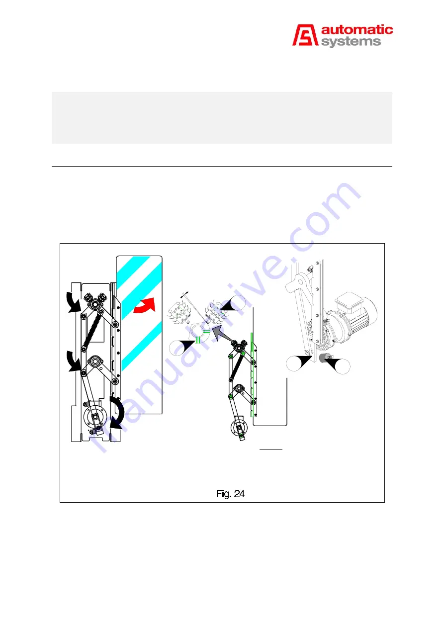
The obstacle is closed in the “0 position” if the points (
x
), (
y
), and (
z
) of the crankshaft-rod device are
perfectly aligned as illustrated in Fig. 24. If the factory-set alignment of these points is correct, the obstacle in
open position (i.e., with passage-way closed) must be locked, with a minimum play, and with motor stopped.
To correct the limit switch cam, proceed as follows:
24:1 Geared motor crank
24:2 Limit switch cam
Legend:
24:3 Opening limit switch (FCO)
24:4 Rubber bumpers
24:1
24:4
24:2
24:3
0.1mm
Passage-way closed
x
y
z
--
Ensure that the equipment is powered off (main magneto-thermal circuit breaker disengaged).
--
Manually set the geared motor crank (
24:1
) to a distance of
40 mm
from the closing abutment (lower
rubber bumper).
--
Loosen the two locking screws of the cam (
24:2
), and slightly move the cam in either direction until the
limit switch is engaged (a click sound can then be heard).


