The informat ion conta ined in th is docu ment is the property of Automatic Syst ems and is conf ident ial . The recip ient shall refr ain from us ing it for any purpose
other than the use of the produ cts or t he e xecut ion of the projec t to wh ich it refers and from commun icat ing it to th ird parties w ithout wr itten pr ior agree m ent
of Automat ic Systems.
RSB76E-MT-EN
p. 30/33
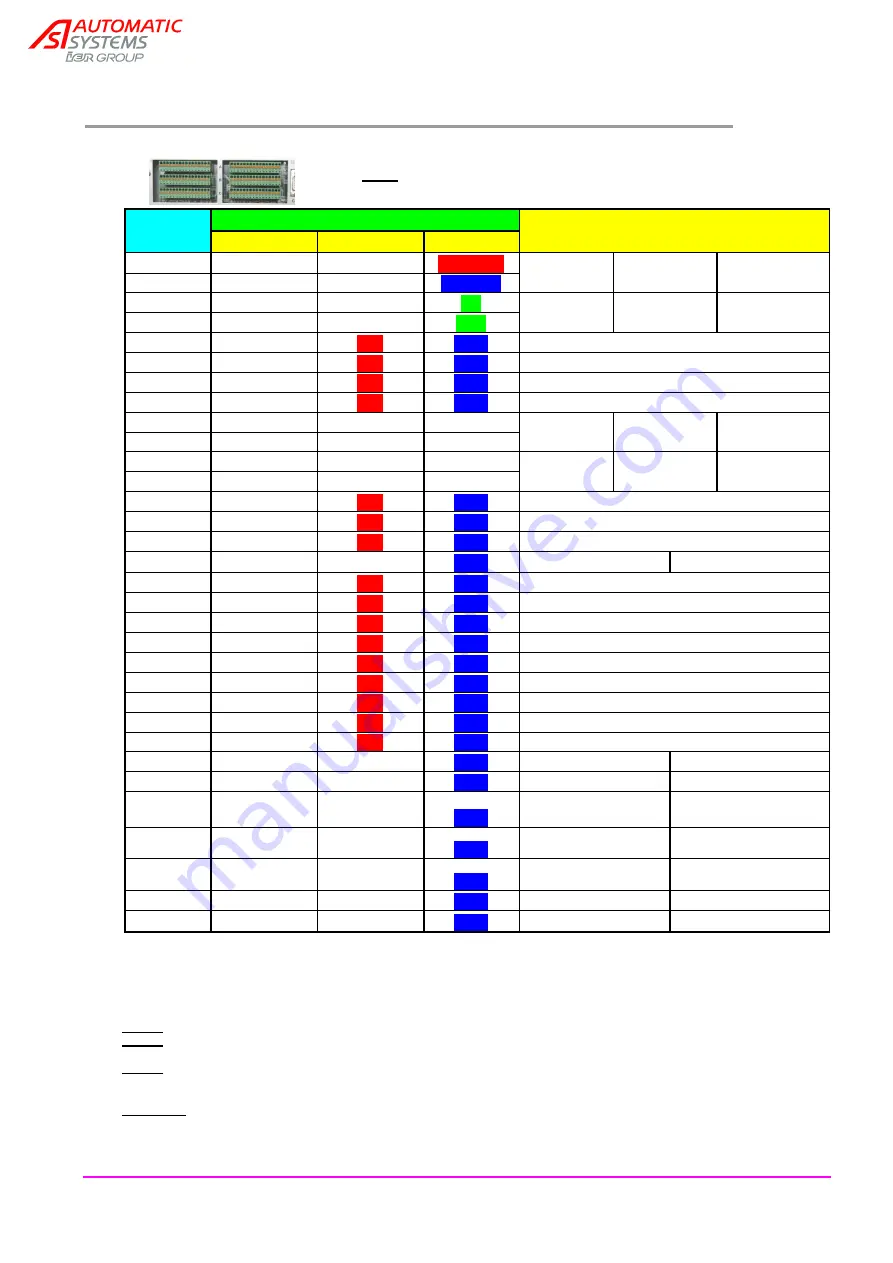
10. CONTROL BOARD TERMINAL ASSIGNMENT
Note
: refer to AS1300 control board manual for more details.
Terminal
Number
Connectors
Assignments
C
B
A
1
BCL1+
BCL3+
24V PWR
PS1***:
induct loop 1
PS3***:
induct loop 3
Power supply:
2
BCL1-
BCL3-
OV PWR
3
BCL2+
BCL4+
PE
PS2***:
induct loop 2
PS4***:
induct loop 4
Ground
4
BCL2-
BCL4-
(PE)
5
DI1
24V
GND
PS1***: photo-cell 1
6
DI2
24V
GND
PS 2***: photo-cell 2
7
DI3
24V
GND
PS3***: photo-cell 3
8
DI4
24V
GND
PS4***: photo-cell 4
9
REL1+
REL3+
REL5+
Relay 1
PS1, NO
Relay 3
RSB Status, NO
Relay 5
Green Entry
10
REL1-
REL3-
REL5-
11
REL2+
REL4+
REL6+
Relay 2
PS2, NO
Relay 4
RSB status, NC
Relay 6
Red Entry
12
REL2-
REL4-
REL6-
13
DI5
24V
GND
Open Command (= obstacle lowering)
14
DI6
24V
GND
Close Command (= obstacle raising)
15
DI7
24V
GND
Stop Command
16
DI8
DI18
GND
Reader A command Reader B command
17
DI9
24V
GND
Lock Open Command
18
DI10
24V
GND
Lock Closed Command
19
DI11
24V
GND
Water Level Sensor
20
DI12
24V
GND
-
21
DI13
24V
GND
Open limit switch of coupled barrier
22
DI14
24V
GND
Close limit switch of coupled barrier
23
DI15
24V
GND
Open LS (= lowered obstacle)
24
DI16
24V
GND
Closed LS (= raised obstacle)
25
DI17
24V
GND
Motor Cut-out
26
DO7
DO8
GND
Ascent Motor
Descent Motor:
27
DO9
24V SECUR
GND
Thermostat
28
DO10 PWM
DO13
GND
Output 10
Obstacle Lighting
*
Output 13
29
DO11 PWM
DO14
GND
Output 11
Flashing Light*
Output 14
30
DO12 PWM
DO15
GND
Output 12
Motor Brake*
Output 15
31
AO1
AO2
GND
Freq. Conv. Speed
32
AI1
AI2
GND
Analogue sensor
* Default values, adjustable through OUTPUT FUNCTION menu.
*** It is possible to connect 4 Presence Sensors (PS), which can be either inductive loops or
photo-electric cells. The loops will be con nected to Terminals 1 to 4, the photo -cells to
Terminals 5 to 8.
Note 1
: a single detector associated to 1 inductive loop will have to be linked to an uneven terminal (PS1 or PS3).
Note 2
: a double detector allows managing 2 loops at a time, but only according to one of the following
combinations: (PS1+PS2) or (PS3+PS4).
Note 3
: It is also possible to combine both kinds of sensors (loops and cells) but not on the same PSx circuit: for
example, if a cell is connected to PS1, a loop cannot be connected to PS 1 nor PS2 (see note 1), but PS3 would be
OK (also PS4 with a double detector).
WARNING
: connecting presence detectors could generate obstacle movement: therefore, turn off the main circuit
breaker before installing presence detectors.
A
B
C
1........................32


