NAM-TRS372-MT-EN-C
p15/38
The information in this document is the property of Automatic Systems and is confidential. The consignee withholds from using it for anything other than the use of the products or the execution of the
project to which they belong and withholds from communicating it to third parties without prior written agreement from Automatic Systems. Document subject to change without prior notice.
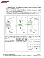
2.5.6. Canopy assembly (option)
Step 1:
Drill five (5) 8mm
[5/16’’] holes (marked X), on both sides of the upper box.
Step 2:
Solution 1:
- Before you proceed to fix the canopy to the housing,
put a line of silicon on the face that comes in contact
with the upper box.
- Using the hardware provided, attach each canopy to
the upper section.
Solution 2:
- Using the hardware provided, attach each canopy to
the upper section.
- Put a line of silicon at the junction where the canopy
and upper box meet.
Line of silicon at junction
(A)
STAINLESS STEEL NUT A4 DIN934 M6
(B)
STAINLESS STEEL FLAT WASHER DIN125 M6
(C)
STAINLESS STEEL TOOTH LOCK WASHER
DIN6798 M6 JZ
(D)
STAINLESS STEEL HEXAGON 1/2 ROUND HEAD
BOLT M6x16
A B
C D
14 x
28 x
14 x
14 x
B
Line of silicon on contact
face
655mm [25.79in]
655mm [25.79in]
450mm [17.71in]
450mm [17.71in]
55mm [2.16in]
5
8
m
m
[2
.2
8
in]
1
7
1
,5
[6
.7
5
in]
58
55mm [2.16in]
5
8
m
m
[
2
.2
8
in]
X
X
X
X
X


