background image

GDO-11 Ero Installation Manual

14

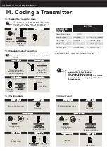
14. Coding a Transmitter

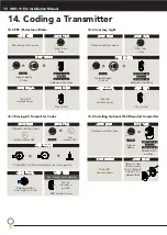
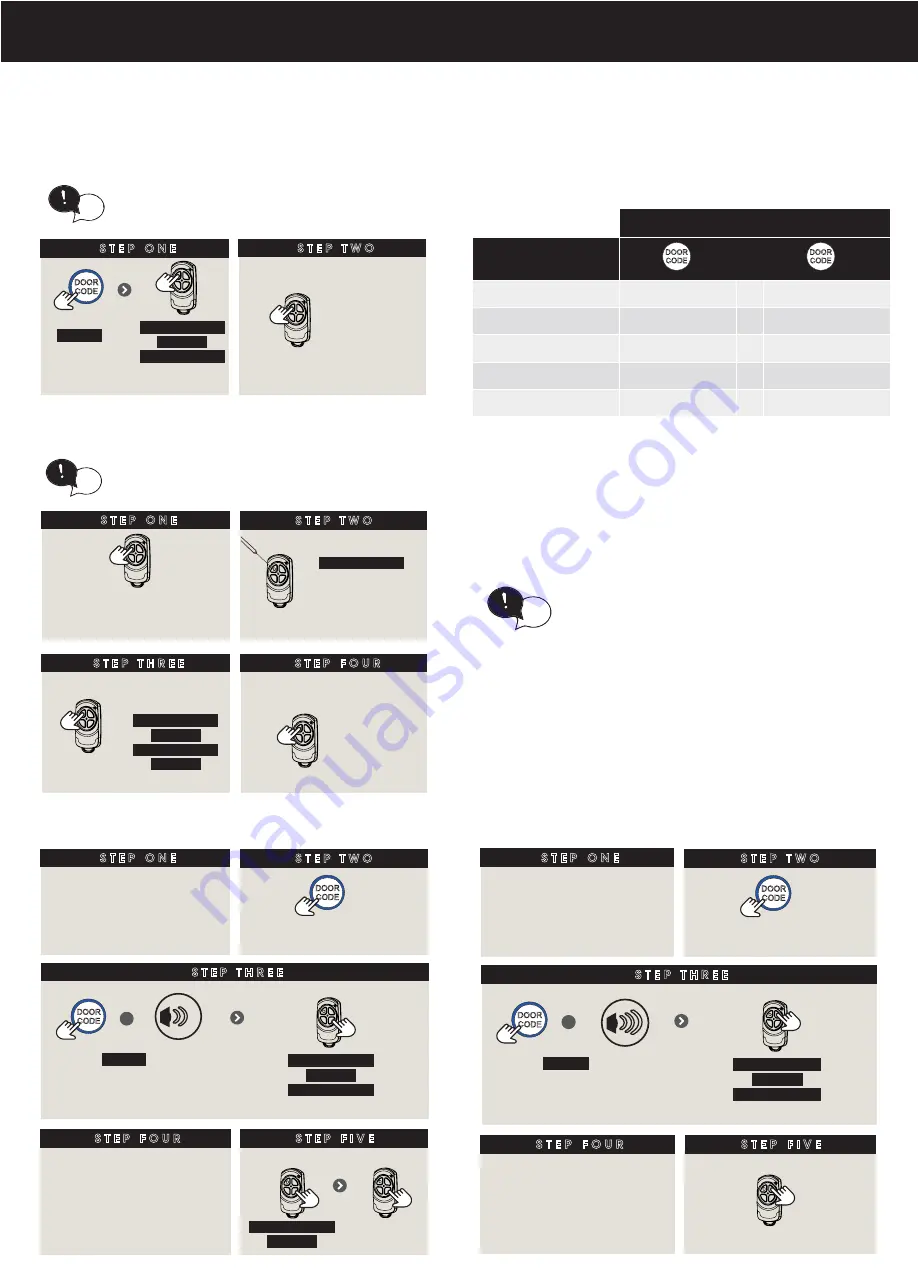
14.1 Storing the Transmitter Code  

The opener can only be operated from remote 

controllers that have been programmed into its 

memory. Up to 64 remotes can be programmed.

tip

S T E P   O N E

S T E P   T W O

Take a pre-coded 

remote and press the 

button to duplicate

R E M O T E L Y   C O D I N G   A   R E M O T E   C O N T R O L

Remotely coding works when you have a 

pre-coded remote control and are in range of the 

opener.

tip

Use a pen,

HOLD for 2 sec

the middle button 

through the 

coding hole

S T E P   T H R E E

Opener flashes & beeps

HOLD for 3 sec

HOLD for 3 sec

RELEASE

Take new 

remote

RELEASE

S T E P   F O U R

Press to test

Opener stops flashing & 

beeping

S T E P   O N E

HOLD

Opener beeps

HOLD for 3 sec

HOLD for 3 sec

RELEASE

Release both 

buttons

S T E P   T W O

Press to test

BUTTON

TRANSMITTER 

FUNCTION

Open / Stop / Close

HOLD

Vacation Mode

Press once 

+

HOLD on second

Aux Output

Press twice

+

HOLD on third

PET (Pedestrian) Mode

Press three times

+

HOLD on fourth

Courtesy Light

Press four times

+

HOLD on fifth

* The button coded for open only function can close the door  if you 

hold the button for 4 seconds, when the door is fully open.

14.2 Remotely Coding Transmitters

The opener can only be operated from remote 

controllers that have been programmed into its 

memory. Up to 64 remotes can be programmed.

tip

S T E P   O N E

S T E P   T W O

Take a pre-coded 

remote and press the 

button to duplicate

R E M O T E L Y   C O D I N G   A   R E M O T E   C O N T R O L

Remotely coding works when you have a 

pre-coded remote control and are in range of the 

opener.

tip

Use a pen,

HOLD for 2 sec

the middle button 

through the 

coding hole

S T E P   T H R E E

Opener flashes & beeps

HOLD for 3 sec

HOLD for 3 sec

RELEASE

Take new 

remote

RELEASE

S T E P   F O U R

Press to test

Opener stops flashing & 

beeping

S T E P   O N E

HOLD

Opener beeps

HOLD for 3 sec

HOLD for 3 sec

RELEASE

Release both 

buttons

S T E P   T W O

Press to test

Remote code set is disabled when:

•  powered by battery backup

•  the service indicator is active

•  when the door is indicating that it was 

prevented from closing by a P.E beam 

being blocked

tip

14.3 Vacation Mode

14.4 Aux Output

V A C A T I O N   M O D E

S T E P   T H R E E

HOLD

Opener beeps 

2 times

HOLD for 3 sec

HOLD for 3 sec

RELEASE

Release all buttons

S T E P   F O U R

Then refit

controls cover

S T E P   O N E

S T E P   T W O

Remove controls cover

Press once

+

S T E P   F I V E

Turn on

HOLD for 4 sec

RELEASE

Turn off

Press, then 

try another 

remote

A U X   O U T P U T

S T E P   T H R E E

HOLD

Opener beeps 

3 times

HOLD for 3 sec

HOLD for 3 sec

RELEASE

Release all buttons

S T E P   F O U R

Then refit

controls cover

S T E P   O N E

S T E P   T W O

Remove controls cover

Press twice

+

S T E P   F I V E

Press to test

Summary of Contents for GDO-11 Ero

Page 1: ...1 GDO 11 Ero S e c t i o n a l D o o r O p e n e r Installation Manual Doc 160424_04 Released 15 12 22 ...

Page 2: ...22 21 3 Battery Disposal 22 21 4 Warranty 22 Installation Instructions Home Owner Instructions WARNING IMPORTANT SAFETY INSTRUCTIONS FOLLOW ALL INSTRUCTIONS SINCE INCORRECT INSTALLATION CAN LEAD TO SEVERE INJURY before installing the drive remove all unnecessary ropes or chains and disable any equipment such as locks not needed for powered operation before installing the drive check that the door ...

Page 3: ...actice correct lifiting techniques when required to lift the door as per installation instructions Fall from ladder Ensure ladder is the correct type for job Ensure ladder is on flat firm ground that will take the weight without the legs sinking Ensure user has 3 points of contact while on ladder Crush injury from unsecured door Place a 2 metre exclusion zone around area under the door while it is...

Page 4: ...uct contains a lithium button coin cell battery in the transmitters If a new or used lithium button coin cell battery is swallowed or enters the body it can cause severe internal burns and can lead to death in as little as 2 hours Always completely secure the battery compartment If the battery compartment does not close securely stop using the product remove the battery and keep it away from child...

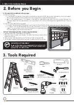
Page 5: ...l support You will need to locate the structural beams in the ceiling which are generally 400mm apart ii does it have exposed beams The opener is mounted to a perforated angle which must be securely fastened to a structural support like the exposed beams You may need to install a 40mm thick board not supplied between structural supports b Look at the wall above the garage door i Is it brick The wa...

Page 6: ...QUIRES properly earthed 3 pin single phase power on the ceiling within an arms length of the opener c Requires a MINIMUM HEADROOM of 57mm between the highest point of the door s travel and the ceiling d Use the diagram below as a reference when completing the installation 1 1 x GDO 11 drive unit 2 1 x Bent arm door attachment 3 1 x Transmitter Holder 4 3 x Transmitters PLUS 5 1 x Track Hardware Ki...

Page 7: ...ay ensue causing serious personal injury and or property damage DO NOT DO IT YOURSELF If sufficient structural support can not be found contact a door profressional for installation DIY c Using step ladder and a level transfer this height to the wall above the door and mark a line 60mm above it across the centre line 7 2 Mounting the Wall Bracket a Draw two lines extending 21 5mm from each side of...

Page 8: ...is placed across the top of the C rail just before the opener Ceiling Beams that run towards the door requires 1 x perforated L shape metal strip and 2 x shorter perforate L shape metal drop down strips Ceiling Beams that run parallel to the door requires 2 x perforated L shape metal strips and 2 x shorter perforate L shape metal drop down strips Not supplied Drill hole at centre of track recommen...

Page 9: ...release the MINUS button and press the OPERATE button once to change the motor s direction 9 1 Mounting the Door Bracket a The door bracket locator 5d is placed over the door bracket 5c on the door s centre line one third down the top panel and mounted using M6 or equivalent screws not supplied b STEEL DOORS ONLY Bracket can be welded in place NOTE If in doubt about the door s strength reinforceme...

Page 10: ... the Open limit the position should be at the height of the garage opening S T E P T W O Switch power on To move the door to the halfway point tip S E T T I N G L I M I T S OR S T E P O N E C L O S E L I M I T P O S I T I O N S T E P T W O HOLD Press to close door S T E P T H R E E W A R N I N G In setting the close limit position do not force the door into the floor with excessive force as this c...

Page 11: ...tiate a re profile LIMITS must already be set opener beeps once RELEASE S T E P T H R E E opener beeps once Then refit controls cover S T E P O N E S T E P T W O C O N T R O L L E R M E M O R Y R E S E T HOLD This will cause all control memory to be set to factory defaults EXCLUDING transmitters history log and cycle counters If limits are already set clear limits first by following Clearing the d...

Page 12: ...a Press and hold the FORCE MARGIN SET Button for six 6 seconds the beeper will sound once b The door will start to move and re calculate force margins The door can move between the open and close limit positions up to four 4 times depending on the position of the door and the power up condition c A single beep will be heard once the process is complete d Test the force again as per Testing Close C...

Page 13: ...ck Network Programmer Solar Shunt Solar Battery Backup 13 2 Auxiliary Output The auxiliary output can be used to control alarm or another garage door opener A valid transmission from the pre coded transmitter will cause the auxiliary output to pulse for approximately 1 one second The maximum DC voltage must not exceed 35 volts DC Maximum current must not exceed 80 ma External device Alarm Door or ...

Page 14: ...that have been programmed into its memory Up to 64 remotes can be programmed tip S T E P O N E S T E P T W O Take a pre coded remote and press the button to duplicate R E M O T E L Y C O D I N G A R E M O T E C O N T R O L Remotely coding works when you have a pre coded remote control and are in range of the opener tip Use a pen HOLD for 2 sec the middle button through the coding hole S T E P T H ...

Page 15: ...ss four times S T E P F I V E Press to test 14 7 Erasing All Transmitter Codes S T E P O N E S T E P T W O Remove controls cover Turn power ON E R A S I N G A L L T R A N S M I T T E R C O D E S Switch power OFF HOLD S T E P T H R E E These LED s will illumminate for 5 secs then go out S T E P F O U R Release button when light turns on Test by pressing a remote Refit controls cover ALL stored code...
Page 16: ...E O P E N E R 2 0 M A N U A L D O O R O P E R AT I O N C A U T I O N W h e n t h e o p e n e r i s m a n u a l l y d i s e n g a g e d t h e d o o r i s n o l o n g e r l o c k e d T o l o c k t h e d o o r m a n u a l l y r e e n g a g e t h e o p e n e r a f t e r t h e d o o r i s c l o s e d T O E N G A G E T H E O P E N E R C A U T I O N D o n o t u s e t h e s t r i n g h a n d l e a s a m e...

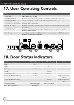
Page 17: ...on has been reached 6 CLOSE LED Red Illuminates and flashes as the door opens closes and remains on when the close limit position has been reached 7 SET Orange Is used during installation The SET button is also used to program the PET Pedestrian position and to re initialise the opener Door Status Indicators OPEN LED green CLOSE LED red Beeper Open On Close On Opening Flashing Closing Flashing Doo...

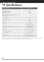
Page 18: ...pe Multi frequency UHF FM 433 47 433 92 434 37MHz Receiver code storage capacity 8 X TriocodeTM 128 4 button Transmitters Coding System TrioCodeTM 128 Type Coding type Non linear encryption algorithm Number of code combinations Over 100 billion random codes Transmitter battery CR2032 3 Volts Courtesy light Festoon style lamp 24volts 15 watts Network connectivity Network compatible requires optiona...

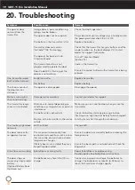
Page 19: ...n is not moving Damage motor assembly Contact your dealer for support The transmitter range varies or is restricted Variations are normal depending on conditions e g temperature or external interference The battery life is exhausted Position of the transmitter in the motor vehicle Make sure you can see the door when you use the transmitter Check the battery status by pressing a button flashing or ...

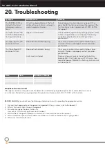
Page 20: ...Remedy The SERVICE LED has started to flash and is beeping numerous times A Fault has been detected The fault will be active each time an attempt is made to operate the door Record opener function How many beeps then press the SET button once to reset the opener If the fault continues to be tripped contact 1300 133 944 for support The Open Green LED and Close Red LED are flashing alternatively Ope...

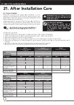
Page 21: ... mounting points along with door bolts screws cables and connectors 3 Adjustment of spring tension to limit spring fatigue 4 Adjustment of opener travel limits and force margin to ensure the door opens and closes to specification 5 Assessment and adjustment of safety components and accessories including safety beams Auto Lock and Safe Lock if installed 6 Assessment of the door alignment and the di...

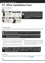
Page 22: ...nd of life batteries Battery recycling recovers non renewable materials such as lead cadmium stella zinc manganese cobalt silver plastics and rare earth elements Removal of batteries and other hazardous household products from household waste facilitates the recovery of organic materials through alternative waste technologies such as composting Batteries and heavy metals are known contaminants in ...

Page 23: ...chnology office location Head Office 6 8 Fiveways Blvd Keysborough 3073 Phone 03 9791 0200 ata aust com au Prefixed trademarks are the property of Automatic Technology Australia Pty Ltd ABN 11 007 125 368 2020 Automatic Technology Australia Pty Ltd ...

Reviews: