background image

GDO-6 EasyRoller Installation Manual

7

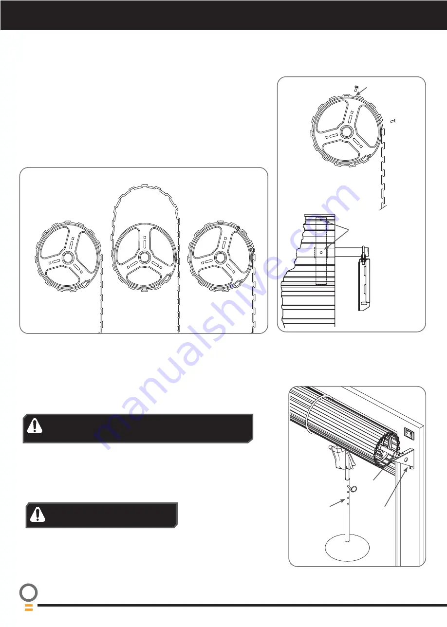
7. Pinning the Door

7.1 Pinning the Door to the drum:

Pinning the door’s curtain to its drum maintains security when the opener is 

closed. If the curtain is not pinned the door can be partially opened manually.  

a. Fully close the door.

b. Mark a minimum of two (2) drill holes on the drum to each end of the door.

c. Drill holes using 3.2mm (

1

/

8

”) drill bit.  

d. Fit M10 x 32mm screws and washers (not supplied) to each of the four (4) 

holes. This screw should be positioned as low as possible in the grove, but 

make sure that it does not alter the curtain’s normal lead in to the guide.

BALLOONING DOOR

PINNED DOOR

FREE DOOR

Without locking 

bars door can be 

lifted

Not pinned and 

without locking 

bars door can be 

lifted

Door secure and 
will not lift

Pin Points

Screw into the 
low part of 

grove

8. Proping the Door

8.1 Prepare the Door:

a. At the end opposite to where the opener will be fitted, check that the U-bolt 

which holds the door axle to the bracket is tightened securely.

b. Open the door completely and tie rope around the door roll. Do not tie the 

rope too tight as damage to the curtain may ensue.  This will stop the door 

unrolling when taken off the bracket

c. At the end where the opener is to be fitted, support the door with a door stand 

or suitable prop. Place a towel between the door and the prop to protect the 

door from damage.

d. At the end where the opener will be fitted use a pencil to mark the position of 

the U-bolt in the door bracket and the position of the door bracket on the wall 

to assist in reassembling.

WARNING! The U-bolt must be done up tightly to ensure 

the stored energy in the springs cannot be unexpectedly 

released.

WARNING!


Make sure the prop is 

snug under the door  and is stable.

U-bolts

Towel

Door stand 
or prop

Door 
bracket

Summary of Contents for GDO-6 EasyRoller

Page 1: ...Doc 160072_04 Released 01 04 20 GDO 6 EasyRoller R o l l i n g D o o r O p e n e r Installation Manual ...

Page 2: ...iary Output 11 12 2 Keyswitch Connection 11 12 3 Remote Aerial 11 13 Auto Close 11 13 1 Safety Beams 11 13 2 Auto Close Option 11 14 Coding a Transmitter 12 14 1 Storing the Transmitter Code 12 14 2 Coding a Button to Enable Vacation Mode 12 14 3 Coding to enable AUX Output 12 14 4 Setting to Operate PET Pedestrian Mode 12 14 5 Coding a Transmitter to the Courtesy Light 12 14 6 Easy Access Transmi...

Page 3: ...tructions Fall from ladder Ensure ladder is the correct type for job Ensure ladder is on flat firm ground that will take the weight without the legs sinking Ensure user has 3 points of contact while on ladder Crush injury from unsecured door Place a 2 metre exclusion zone around area under the door while it is unsecured Do not move under a door while it is on the door support or ladder Follow the ...

Page 4: ...R 2 x PTX 5V2 Transmitters GDO 6V3 4 1 x Weight Bar Fastner Bag 5 2 x Nilock Nut 6 2 x 3 16 x 1 2 flat washers 7 2 x Pan Head Screw M4 x 50mm 1 2 3 5 6 7 4 Screwdrivers Adjustable End Wrench Sockets and Wrench Pencil Rope Drill Towel Self tapping Screws and Washers M10 x 32mm Stepladder Door Stand or suitable prop 3 Tools Required ...

Page 5: ...be fitted at least 135mm to the bracket is required Therefore the recommended sideroom from the edge of the door curtain is 135mm to the inside of the door bracket and 175mm to the wall as per diagram 4 Setup Requirements 4 1 The Opener a MUST BE installed in a dry position protected from weather Moisture or corrosion not covered by Warranty b Is factory set for RIGHT HAND SIDE installation from i...

Page 6: ... M4x50mm Pan Head Screw 7 and the two 2 Flat Washer 6 and the two 2 M4 Nilock Hex nut 5 d Check that the door is still balanced and smooth If not then the door may require servicing 4 2 7 5 Door Preparation 5 1 Prepare the Door a Clean the guides if there is any oil or wax present using a suitable white spirit The only lubricant suitable for use on door guides is silicon spray DO NOT use WD 40 RP ...

Page 7: ...into the low part of grove 8 Proping the Door 8 1 Prepare the Door a At the end opposite to where the opener will be fitted check that the U bolt which holds the door axle to the bracket is tightened securely b Open the door completely and tie rope around the door roll Do not tie the rope too tight as damage to the curtain may ensue This will stop the door unrolling when taken off the bracket c At...

Page 8: ... drive gear rotates freely by pulling the string handle down there will be a click to disengage opener Then move the forks from side to side by hand c Slide the opener over the door axle and into the drum of the door as shown d Push the opener in as far as possible without interfering with the curtain SO ONE OF THE DOOR DRUM S WHEEL SPOKES IS BETWEEN THE OPENER S DRIVE FORKS e Raise the door off t...

Page 9: ... will inch the door open f If the door overshoots press the CLOSE button to move the door in the close direction g When the door is at the desired open position press the SET button WARNING In setting the close limit position do not force the door into the floor with excessive force as this can interfere with the ease of operation of the manual release mechanism h The door will now automatically c...

Page 10: ...nd hold the FORCE MARGIN SET Button for six 6 seconds the beeper will sound once b The door will start to move and re calculate force margins The door can move between the open and close limit positions up to four 4 times depending on the position of the door and the power up condition c A single beep will be heard once the process is complete d Test the force again as per Testing Close Cycle and ...

Page 11: ...has the input to connect bell switch or keyswitch to open or close the door 13 Auto Close 13 1 Safety Beams A Safety Beam Kit may be fitted to this opener When this option is fitted the operation of this device is such that if an object i e car child etc blocks the Infra Red beam then the garage door opener will not close the door automatically If the Safety Beam is fitted but not operating correc...

Page 12: ...utton for two seconds 14 3 Coding a Transmitter to enable AUX Output Briefly press the DOOR CODE button two 2 times then press it again and hold the opener will beep three 3 times on the third press a Press one of the four buttons on the transmitter for two 2 seconds pause for two 2 seconds then press the same button again for two 2 seconds b Release the DOOR CODE button c Press the transmitter bu...

Page 13: ...hold again for two seconds and then release d Wait for ten 10 seconds and then press the new transmitter s button to test 14 8 Erasing a Stored Transmitter Code a Select the transmitter you want to delete b Press and hold the DOOR CODE BUTTON c Press the transmitter button you would like to delete for two seconds pause for two seconds press again for two seconds and then release d Release the DOOR...

Page 14: ...xtreme tension and can cause serious personal injury DO NOT attempt any garage door adjustment DO NOT use if repair or adjustment is needed Call for a professional garage door service CAUTION Emergency access If your garage has no pedestrian entrance door an emergency access device should be installed This accessory allows manual operation of the garage door from outside in case of power failure E...

Page 15: ...ease is easy to operate No more than 20kg of force should be required to disengage the door using the manual release cord If excessive force is required reset the close limit position Section 10 Resetting Door Limits 17 Operating your Opener 17 1 To Operate the opener a Press the programmed transmitter button until your door begins to move usually 2 seconds Make sure you can see the door when you ...

Page 16: ...tes and flashes as the door opens and remains on when the open limit position has been reached 6 DOOR STATUS LED Yellow Illuminates when Service is due 7 CLOSE LED Red Illuminates and flashes as the door opens closes and remains on when the close limit position has been reached Door Status Indicators OPEN LED green CLOSE LED red Beeper Open On Close On Opening Flashing Closing Flashing Door travel...

Page 17: ...uency UHF FM 433 47 433 92 434 37MHz Receiver code storage capacity 64 X TriocodeTM 128 4 button Transmitters 14 X TriocodeTM 128 4 button Transmitters Coding System TrioCodeTM 128 Type TrioCodeTM 128 Type Coding type Non linear encryption algorithm Non linear encryption algorithm Number of code combinations Over 100 billion random codes Over 100 billion random codes Transmitter battery CR2032 3 V...

Page 18: ... transmitter range varies or is restricted Variations are normal depending on conditions e g temperature or external interference The battery life is exhausted Position of the transmitter in the motor vehicle Make sure you can see the door when you use the transmitter Check the battery status by pressing a button flashing or no light requires battery to be changed Aim the transmitter through the w...

Page 19: ... away any obstructions and test door closes correctly If door is damaged contact your door professional Remove all power sources including the battery backup Wait till all lights are out 10 15 secs then reconnect power If Red LED is flashing limits are not set Reset Limits 21 Troubleshooting If You Need a Service Call If the opener needs a service please call the dealer who installed the garage do...

Page 20: ...oor mounting points along with door bolts screws cables and connectors 3 Adjustment of spring tension to limit spring fatigue 4 Adjustment of opener travel limits and force margin to ensure the door opens and closes to specification 5 Assessment and adjustment of safety components and accessories including safety beams Auto Lock and Safe Lock if installed 6 Assessment of the door alignment and the...

Page 21: ...smitter button Check Light Status table to determine if battery needs replacing Light Status Battery Status Solid OK Flashing Requires replacement No light Requires replacement Use a pen to push the battery down through the side opening to release battery Use finger nails to separate the transmitter casing to expose circuit board Use a non metallic object e g pen to remove the battery Some batteri...

Page 22: ... Technology office location Head Office 6 8 Fiveways Blvd Keysborough 3073 Phone 03 9791 2000 ata aust com au Prefixed trademarks are the property of Automatic Technology Australia Pty Ltd ABN 11 007 125 368 2020 Automatic Technology Australia Pty Ltd ...

Reviews: