16
GDO-7v2 SecuraLift®
Owner Installation Instructions
Setting Limits
20
fi g
21
fi g
NOTE:
If P.E. Beams are to be used they must be
installed before setting the travel limits.
Step 15.1 - Remove Controls Cover
Remove the controls cover to access the control panel
Replace it when setup is completed.
Step 15.2 - Connect Power to the Powerhead
Plug the power cord into a mains point and switch power
on. The red CLOSE LIMIT LED will be fl ashing.
WARNING:
The safety obstruction detection
system is inoperable while MINUS (-) and PLUS (+)
drive buttons are being used and travel limits are
not set.
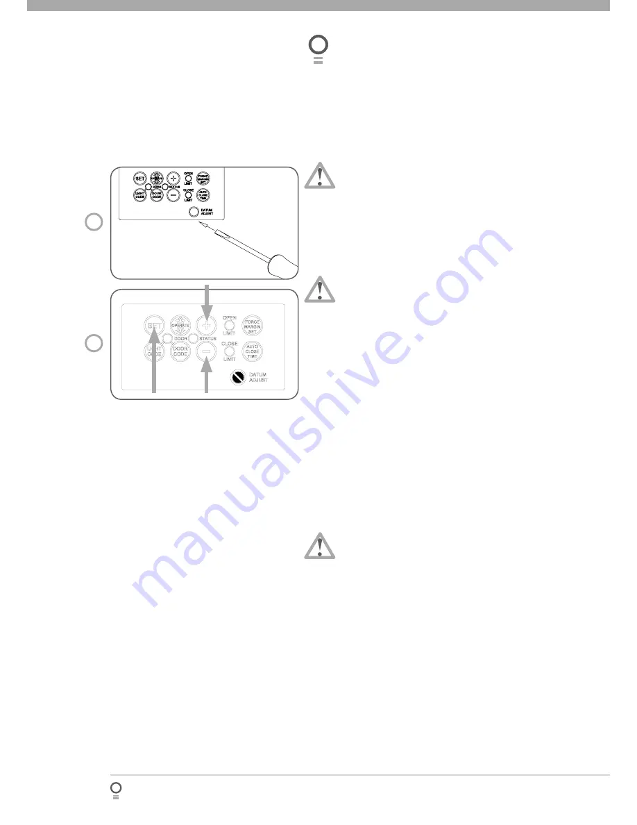
Step 15.3 - Set the Datum Position
Press and hold the MINUS (-) or PLUS (+) buttons to
move the door to the halfway position. Ensure that
the door, shuttle and chain index are engaged.
Using a small screwdriver, turn the DATUM ADJUST
screw until the STATUS LED comes on
(Fig 20).
If the STATUS LED is already illuminated when
the door is halfway up, turn the DATUM ADJUST
screw until the light goes off, then turn back one
notch to illuminate again.
Step 15.4 - Set the Limits Positions
Press and hold the MINUS (-) button until the door
reaches the desired close limit position. Single
presses will the inch the door closed
(Fig. 21)
.
Press the LIMIT SET button to store the close position
into memory
(Fig. 21)
Press and hold the PLUS (+) button until the door
reaches the desired open limit position. Single
presses will the inch the door open
(Fig. 21)
.
IMPORTANT WARNING:
The door will
automatically close, open and close again
once
Step 15.4(c) is performed
. Ensure that no persons
or objects are in the door’s path.
Press the LIMIT SET button to store the close position
into memory
(Fig. 27)
.
The door will now automatically close and open to
calculate the safety obstruction settings. After this, the
opener can be operated with the OPERATE button.
Step 15.5 - Resetting the Door Limit Positions
Limit positions can be deleted by the following steps:
Press and hold the MINUS (-) button for six (6)
seconds until you hear three beeps and the CLOSE
LIMIT LED starts to fl ash
(Fig. 21)
.
Release the CLOSE button.
Repeat Steps 15.1 to 15.4 to set new travel limit
positions..
a.
b.
»
a.
b.
c.
d.
e.
a.
b.
c.


