6 - 8 Fiveways Boulevard, Keysborough, VIC, Australia 3173
P: 1300 133 944 E: sales@automatictechnology.com.au
W: www.automatictechnology.com.au
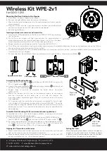
Wireless Kit WPE-2v1
for GDO-12V1
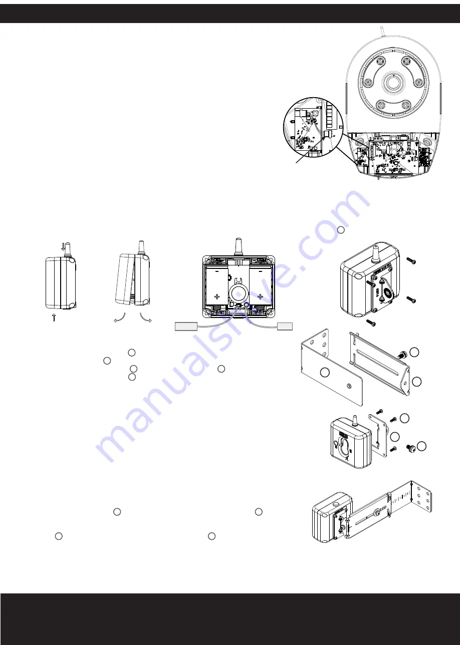
Receiver
RESET
LED
Apply pressure here
Pull covers apart
Inserting batteries into receiver and transmitter
a. Insert two (2) C-Type batteries in the Receiver (WPB-4.02 RX) by removing
the front cover.
b. The LED on the receiver will light up and after the communication is
established between the receiver and base station the LED on the base
station and the receiver will turn off. This can take up to 60secs.
Mounting the Base Station to the Opener
a. Disconnect the power supply to the opener.
b. Remove the light diffuser cover via screw at the bottom.
c. Mount the base station board next to the control board as shown using the
screw supplied.
d. Plug the harness into the 4 pin connector on the base station board and
connect the harness to the ACC pin on the control board.
e. Refit the light diffuser.
ACC Pin
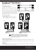
Assembling the Mounting Bracket
a. Attach the PE 2000TS Bracket
1
to the Receiver (WPB-4.02 RX) using four (4)
M3 x 5 Taptite screws
4
.
b. Connect the mounting bracket
3
to the adjustment bracket
2
with two (2) of
the M5 x 10 Pan Head Screws
5
.
c. Repeat steps (a) and (b) to assemble the Safety Beam Transmitter
(WPB-4.02TX).
d. Mount the receiver on the side of the doorway closest to the opener
and the transmitter on the other side in line with the receiver. The
mounting surface should be rigid. Affix with a minimum of four (4) screws
(not supplied).
e. ATA recommends the transmitter and receiver are placed in line of sight,
with the beam 100mm above the ground level (as per AS60335). This can be
achieved by ensuring the bottom of the receiver and transmitter are 65mm
above ground level. They should also be placed as close as possible to the
door opening.
4
1
5
2
3
5
Right side
bracket
Right side
bracket
assembled
Assemble Flush Mounting Kit (for minimum sideroom applications)
For applications which have limited space available or certain environmental
factors a flush mounting kit can be used.
a. Attached the transmitter (WPB-4.02TX) and receiver (WPB-4.02RX) to the
two (2) PEB4-W1 Bracket
5
with the eight (8) M3 x 8 Taptite screws “P”
6
.
b. Ensure to take note of the ATA recommendation in step (e) above and fix the
TX and RX to the wall or rigid surface using the two (2) 6.9 x 25 plastic wall
plugs
8
(if wall) and two (2) M6 x 25 self tapping screws
7
.
Aligning the Transmitter and Receiver
a. Make horizontal and/or vertical adjustment on the transmitter until the red
LED on the receiver stays on, this indicates alignment.
b. Make horizontal and/or vertical adjustment on the receiver until the red LED
on the transmitter stays on, this indicates alignment.
Setting the limits
After aligning the safety beams, refer to the openers
manual to set the travel limits. If Opener already
installed, install the safety beams then run the door
for 2 cycles for the opener to update details.
c. Repeat step (a) to insert batteries into the Transmitter (WPB-4.02 TX).
d. The LED on the transmitter will light up and after communication is established between the transmitter and base station the LED on
the transmitter and on the receiver will start to flash.
e. The flashing indicates the link is established between the transmitter and base station, receiver and base station, but receiver and
transmitter are not yet alligned.
f. Put cover back on Transmitter and Receiver and secure with eight (8) M3 x 12 taptite screws (black)
9
.


