Right side
bracket
assembled
NOTE:
Mount the receiver on the side of the doorway closest to the
base station.
NOTE:
Mount the receiver on the side of the doorway / gateway
closest to the opener / console.
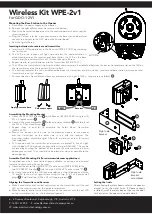
Assembling the Mounting Bracket
Assemble the mounting bracket as per font page instructions.
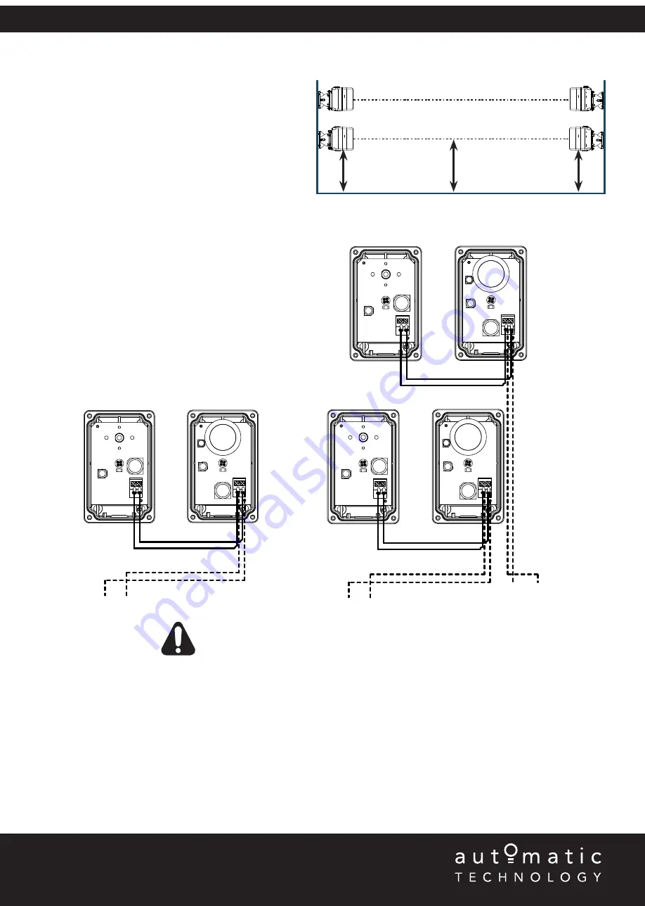
NOTE:
When using two (2) sets of Safety Beams within the
opening you must alternative the configuration. See diagram.
ATA recommends the transmitter and receiver are placed in
line of sight, with the beam 100mm above the ground level (as
per AS60335). This can be achieved by ensuring the bottom
of the receiver and transmitter are 65mm above ground level.
They should also be placed as close as possible to the door /
gate opening.In industrial applications it is recommended that
multiple Safety Beams are fitted.
TRANSMITTER
RECEIVER
0V SB1 OR SB2
TX - 1
RX - 1
TX - 2
RX - 2
65mm
Floor Level
100mm
65mm
WARNING!
When using PE Beams, the doorway must be clear of all
obstructions and persons at all times. The location of the beams and
manner in which it is installed might not give safety protection at all
times. Check to make sure that the height of the beam and type used
give maximum protection possible.
TRANSMITTER
TRANSMITTER
TRANSMITTER
RECEIVER
RECEIVER
0V SB1
0V SB2
One (1) set
Two (2) sets
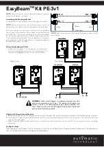
EasyBeam
TM
Kit PE-3v1
Wiring the EasyBeam
TM
PE-3v1
a. Connect the EasyBeam
TM
to the opener / console as per
the first wiring diagram for one (1) set of safety beams or
second wiring diagram for two (2) sets of safety beams.
Aligning the Transmitter and Receiver
a. Power up the opener with the
safety beams
connected. The green LED on the transmitter should turn ON to indicate power is present.
b. If the receiver is connected to power and the red LED is flashing while the green LED on the transmitter is on, the transmitter and
receiver are not aligned.
c. Make horizontal and/or vertical adjustment on the transmitter and/or receiver until the red LED on the receiver turns on, indicating
alignment.
Setting the limits
After aligning the safety beams, refer to the openers manual to set the travel limits. If Opener already installed, install the safety beams
then run the door for 2 cycles for the opener to update details.


