Chapter 1: Overview and Component Specifications
1–8
DURA
pUlse
Drives Dynamic Braking User Manual – 2nd Ed., Rev.C – 06/14/2019
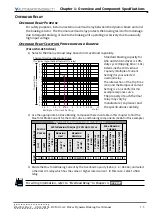
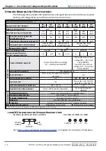
Dynamic Braking Unit Specifications
The following table provides the specifications and applications for the
dUra
pUlse
dynamic
braking units designed for use with GS3 and GS4 series AC drives.
D
ynAmiC
B
rAkinG
U
nit
S
peCifiCAtionS
Braking Unit Part Number
GS-
1DBU
GS-
2DBU
GS-
3DBU
GS-
4DBU
GS-
5DBU
GS-
6DBU
GS-
7DBU
Nominal Voltage (VAC)
230
460
Max Motor Capacity (hp/[kW])
20
[15]
30
[22]
40
[30]
60
[45]
150
[110]
200
[160]
250
[185]
Output Ra
ting
Max Discharge Current (A)
@ 10% Duty Cycle*
40
60
40
60
126
190
225
Continuous Discharge Current (A)
15
20
15
18
45
50
100
Braking Startup Voltage (VDC)
330/345/360/
380/400/415 ±3V
660/690/720/
760/800/830 ±6V
618/642/667/690/
725/750 ±6V
Maximum On-Time (s)
10
Input DC Voltage (VDC)
200–415
400–830
400–750
Min Equivalent Resistor
for Each Braking Unit (Ω)
10
6.8
20
13.6
6
4
3.4
Pr
ote
ction
Power CHARGE Lamp/LED
Comes ON until DC bus voltage
(+P – -N) drops below 50VDC
Comes ON when DC bus
voltage (DC+ – DC-) rises
above 300VDC.
Goes OFF when DC bus
voltage (DC+ – DC-) drops
below 100VDC.
Braking ACT Lamp/LED
ON during braking
Fault ERR Lamp
ON if an over-temperature fault has
occurred
n/a
Overcurrent Level LED (A)
n/a
190
290
340
Overheat LED
n/a
Comes ON > 176°F [80°C];
Goes OFF < 149°F [65°C]
Heat Sink Overheat Temperture
203°F [95°C]
n/a
Alarm Output Relay Contact
5A @ 120VAC/28VDC (RA,RB,RC)
3A @ 250VAC/28VDC
(RA,RC)
Envir
onment
Installation Location
indoor (no corrosive gases; no metallic dust)
Operating Temperature
14°F to 122 °F [-10 to +50 °C]
Storage Temperature
-4 to +140 °F [-20 to +60 °C]
Humidity
less than 90% RH, non-condensing
Vibration
9.8 m/s
2
[1G] under 20Hz ; 2m/s
2
[0.2G] at 20–50 Hz
Mechanical Configuration
IP50 wall-mount enclosed
IP10 wall-mount enclosed
* 10% Duty Cycle with maximum ON (braking) time of 10 seconds
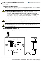
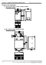
Lamp/LED Indicators for Dynamic Braking Units
CHARGE
ACT
OC
OH
GS-5DBU, GS-6DBU, GS-7DBU
CHARGE
(GREEN)
ACT
(YELLOW)
ERR
(RED)
GS-1DBU, GS-2DBU, GS-3DBU, GS-4DBU
See “
DBU Jumper and Wiring Terminal Locations
” in Chapter 3 for locations of indicators.
Summary of Contents for DURA PULSE GS-2DBU
Page 1: ...Dynamic Braking User Manual GS DB_UMW...
Page 2: ...BLANK PAGE...
Page 6: ...W 4 DURApulse Drives Dynamic Braking User Manual 2nd Ed Rev C 06 14 2019 BLANK PAGE...
Page 49: ...2nd Ed Rev C 06 14 2019 DURApulse Drives Dynamic Braking User Manual BLANK PAGE...
Page 50: ...DURApulse Drives Dynamic Braking User Manual 2nd Ed Rev C 06 14 2019...


