Chapter 3: Component Configuration and Wiring
DURA
pUlse
Drives Dynamic Braking User Manual
3–5
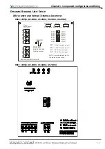
DBU Master/Slave Jumper Settings
The MASTER/SLAVE jumper on the
DURa
pUlse
dynamic braking unit has a factory default
setting as a MASTER. If the application of the
DURa
pUlse
AC drive requires the use of more
than one DBU, then the power terminals of the multiple units are wired in parallel and the
first unit is set to MASTER while all remaining units are set to SLAVE. The jumper settings
along with the wiring between the MASTER/SLAVE (M1, M2, S1 & S2) terminals allows the
multiple braking units to synchronize the power dissipation between braking units. This
assures each unit is dissipating an equivalent amount of energy to allow rapid deceleration
of the motor.
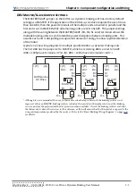
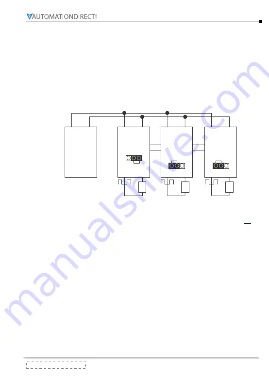
Typical one-line wiring diagram for multiple parallel DURA
pUlse
dynamic braking units�
The first DBU has the jumper set to MASTER, while the remaining DBUs are set to SLAVE�
(DBU ≤ 100hp have ter(P) & -(N); DBU > 100hp have terminals DC+ & DC-)
DURApulse
AC Drive
M1
M2
MASTER
B1 B2
O.L.*
M1
M2
B1 B2
S1
S2
B1 B2
S1
S2
SLAVE
SLAVE
+(P)
-(N)
+(P)
-(N)
+(P)
-(N)
+(P)
-(N)
DC+
DC-
DC+
DC-
DC+
DC-
BR
BR
BR
O.L.*
O.L.*
* Although it is recommended, the use of a thermal overload relay in line with the braking resistor is not
required. GS-xxxx-BR-ENC braking resistors include a thermostat for thermal protection of the braking
resistor, and are the preferred method of protection when available. Orient the braking resistors such that
the thermostat is above the resistors in the enclosure, as this will ensure that the thermostat is exposed to the
for details.
Summary of Contents for DURA PULSE GS-2DBU
Page 1: ...Dynamic Braking User Manual GS DB_UMW...
Page 2: ...BLANK PAGE...
Page 6: ...W 4 DURApulse Drives Dynamic Braking User Manual 2nd Ed Rev C 06 14 2019 BLANK PAGE...
Page 49: ...2nd Ed Rev C 06 14 2019 DURApulse Drives Dynamic Braking User Manual BLANK PAGE...
Page 50: ...DURApulse Drives Dynamic Braking User Manual 2nd Ed Rev C 06 14 2019...

