Chapter 3: Component Configuration and Wiring
3–8
DURA
pUlse
Drives Dynamic Braking User Manual – 2nd Ed., Rev.C – 06/14/2019
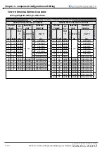
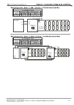
DBU Wiring Terminal Specifications
b
raking
u
nit
w
iring
t
erminal
s
Pecifications
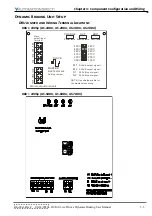
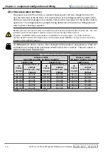
Braking Unit Models: GS-1DBU, GS-2DBU, GS-3DBU, GS-4DBU
Circuit
Terminal Mark
Wire Size
Screw
Torque
Power Input Circuit
+(P), -(N)
10–12 AWG
[3.5–5.5 mm
2
]
M4
15.6 in·lb
[18 kg·cm]
Braking Resistor
B1, B2
10–12 AWG
[3.5–5.5 mm
2
]
M4
15.6 in·lb
[18 kg·cm]
Slave Circuit
Output
M1, M2
18–20 AWG
[0.8–0.5 mm
2
]
(with shielded wires)
M2
3 in·lb
[4 kg·cm]
Input
S1, S2
Fault Circuit
RA, RB, RC
18–20 AWG
[0.8–0.5 mm
2
]
M2
3 in·lb
[4 kg·cm]
Braking Unit Models: GS-5DBU, GS-6DBU, GS-7DBU
Circuit
Terminal Mark
Wire Size
Screw
Torque
Power Input Circuit
DC+, DC-
4–6 AWG
[21.2–13.3 mm
2
]
M8
26 in·lb
[30 kg·cm]
Braking Resistor
B1, B2
4–6 AWG
[21.2–13.3 mm
2
]
M8
26 in·lb
[30 kg·cm]
Slave Circuit
Output
M1, M2
18–20 AWG
[0.8–0.5 mm
2
]
(with shielded wires)
M2
3 in·lb
[4 kg·cm]
Input
S1, S2
Fault Circuit
RA, RC
18–20 AWG
[0.8–0.5 mm
2
]
M2
3 in·lb
[4 kg·cm]
Summary of Contents for DURA PULSE GS-2DBU
Page 1: ...Dynamic Braking User Manual GS DB_UMW...
Page 2: ...BLANK PAGE...
Page 6: ...W 4 DURApulse Drives Dynamic Braking User Manual 2nd Ed Rev C 06 14 2019 BLANK PAGE...
Page 49: ...2nd Ed Rev C 06 14 2019 DURApulse Drives Dynamic Braking User Manual BLANK PAGE...
Page 50: ...DURApulse Drives Dynamic Braking User Manual 2nd Ed Rev C 06 14 2019...

