Chapter 1: Overview and Component Specifications
DURA
pUlse
Drives Dynamic Braking User Manual
1–5
Overload Relay
Overload Relay Purpose
For safety purposes, install an external overload relay between the dynamic brake unit and
the braking resistor. The thermal overload relay protects the braking resistor from damage
due to frequent braking, or due to the braking unit operating excessively due to unusually
high input voltage.
Overload Relay Selection Procedure and Example
(For a GS4-4150 drive)
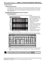
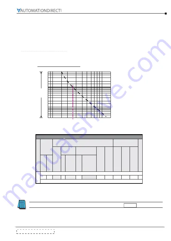
1) Select a thermal overload relay based on its overload capability.
60
40
30
20
10
8
3
2
4
6
1
0.8
0.6
0.4
0.3
0.8 1
1.5
2
3
4
5 6
8
10
15
7
9
Multiple of Current Setting
xln (A)
Tripping Time
seconds
2.6
Thermal Overload Response Curve
(for typical hypothetical thermal O/L relay)
Standard braking capacity for
GS3 and GS4 AC drives is 10%
duty cycle (tripping time = 10s).
Determine the 10s Overload
Capacity (Multiple of Current
Setting) for your selected
overload relay.
The intersection of the Trip Time
(10s) and the Multiple of Current
Setting is 2.6 (or 260%) for this
example response curve.
The property of each thermal
relay may vary by
manufacturer, so please read
the specifications carefully.
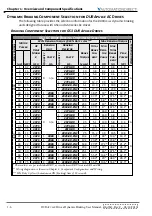
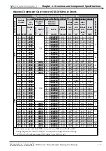
2) Use the appropriate AC Drive Braking Component Selection table in this chapter to find the
Max Total Brake Current for the motor, drive, and braking components (126A for this example).
GS
4
AC D
rive
B
rAkinG
C
omponent
S
eleCtion
Drive V
ol
ta
ge
Motor
Power
125% Braking Torque @ 10% Duty Cycle
Max Braking
Torque
W
iring Dia
g.
AC Drive Model
# GS4-
Braking
Unit
Braking
Resistor
Br
ake T
or
que
(k
g·m)
To
tal Br
ake
Current (A)
Min Re
sis
tor
Val
ue (Ω)
Max T
ot
al Br
ake
Current (A)
Pe
ak Po
wer (kW)
(hp)
(kW)
Qu
antity
Par
t #
GS-
Qu
antity
Par
t #
GS-BR-
460V
150 110 4150 1 5DBU 10 1K2W015 74.5 126
6.0
126 95.8 L
3) Divide the Max Total Braking Current by the Overload Capacity (126A / 2.6 = 48.46A), and select
a thermal O/L relay which has the same or higher rated current.
In this case, select a 50A
relay.
For wiring information, refer to “Overload Relay” in Chapter 3, page 3–2.
Summary of Contents for DURA PULSE GS-2DBU
Page 1: ...Dynamic Braking User Manual GS DB_UMW...
Page 2: ...BLANK PAGE...
Page 6: ...W 4 DURApulse Drives Dynamic Braking User Manual 2nd Ed Rev C 06 14 2019 BLANK PAGE...
Page 49: ...2nd Ed Rev C 06 14 2019 DURApulse Drives Dynamic Braking User Manual BLANK PAGE...
Page 50: ...DURApulse Drives Dynamic Braking User Manual 2nd Ed Rev C 06 14 2019...

