Chapter 1: Overview and Component Specifications
DURA
pUlse
Drives Dynamic Braking User Manual
1–7
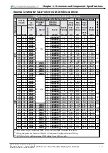
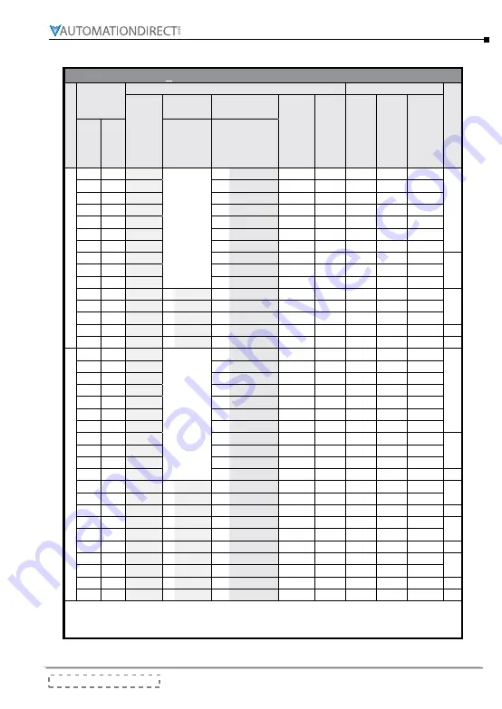
Braking Component Selection for GS4 DURApulse Drives
GS
4
AC D
rive
B
rAkinG
C
omponent
S
eleCtion
Drive V
ol
ta
ge
Motor
Power
125% Braking Torque @ 10% Duty Cycle***
Max Braking Torque
W
iring Dia
gr
am **
AC
Drive
Model
#
GS4-
Braking
Unit
Braking
Resistor
Brake
Torque
(kg·m)
Total
Brake
Cur-
rent
(A)
Min
Resis-
tor
Value
(Ω)
Max
Total
Brake
Cur-
rent
(A)
Peak
Power
(kW)
(hp) (kW)
Qu
antity
Part #
GS-
Qu
antity
Part #
GS-BR-
230V
1
0.7
21P0
0
n/a
1
080W200
0.5
1.9
63.3
6
2.3
A
2
1.5
22P0
1
200W091
1.0
4.2
47.5
8
3.0
3
2.2
23P0
1
300W070
1.5
5.4
38.0
10
3.8
5
3.7
25P0
1
400W040
2.5
9.5
19.0
20
7.6
7.5
5.5
27P5
1
1K0W020
3.7
19
14.6
26
9.9
10
7.5
2010
1
1K0W020
5.1
19
14.6
26
9.9
15
11
2015
1
1K5W013
7.5
29
12.6
28
10.6
20
15
2020
2
1K0W4P3
10.2
44
8.3
46
17.5
B
25
18
2025
2
1K0W4P3
12.2
44
8.3
46
17.5
30
22
2030
2
1K5W3P3
14.9
58
5.8
66
25.1
40
30
2040
2
1DBU
4
1K0W5P1
20.3
75*
4.8*
80*
30.4*
G
50
37
2050
2
2DBU
4
1K2W3P9
25.1
97*
3.2*
120*
45.6*
60
45
2060
2
2DBU
4
1K5W3P3
30.5
118*
3.2*
120*
45.6*
75
55
2075
3
2DBU
6
1K2W3P9
37.2
145*
2.1*
180*
68.4*
J
100
75
2100
4
2DBU
8
1K2W3P9
50.8
190*
1.6*
240*
91.2*
K
460V
1
0.7
41P0
0
n/a
1
080W750
0.5
1
190
4
3.0
A
2
1.5
42P0
1
200W360
1
2.1
126.7
6
4.6
3
2.2
43P0
1
300W250
1.5
3
108.6
7
5.3
5
3.7
45P0
1
400W150
2.5
5.1
84.4
9
6.8
7.5
5.5
47P5
1
1K0W075
3.7
10.2
54.3
14
10.6
10
7.5
4010
1
1K0W075
5.1
10.2
47.5
16
12.2
15
11
4015
1
1K5W043
7.5
17.6
42.2
18
13.7
20
15
4020
2
1K0W016
10.2
24
26.2
29
22.0
B
25
18
4025
2
1K0W016
12.2
24
23.0
33
25.1
30
22
4030
2
1K5W013
14.9
29
23.0
33
25.1
40
30
4040
4
1K0W016
20.3
47.5
14.1
54
41.0
C
50
40
4050
1
4DBU
4
1K2W015
25.1
50*
12.7*
60*
45.6*
E
60
45
4060
1
4DBU
4
1K5W013
30.5
59*
12.7*
60*
45.6*
75
55
4075
2
3DBU
8
1K0W5P1
37.2
76*
9.5*
80*
60.8*
H
100
75
4100
2
4DBU
8
1K2W015
50.8
100*
6.3*
120*
91.2*
I
125
90
4125
2
4DBU
8
1K5W013
60.9
117*
6.3*
120*
91.2*
150 110
4150
1
5DBU
10
1K2W015
74.5
126*
6.0*
126*
95.8*
L
175 132
4175
1
6DBU
12
1K5W012
89.4
190*
4.0*
190* 144.4* M
200 160
4200
1
6DBU
12
1K5W012
108.3
190*
4.0*
190* 144.4*
250 185
4250
1
7DBU
14
1K5W012
125.3
225*
3.4*
225* 172.1* N
300 220
4300
2
5DBU
20
1K2W015
148.9
252*
3.0*
252* 190.5* O
* These values are per individual DBU, as seen between DBU terminals B1 and B2.
** Wiring diagrams are shown in Chapter 3: Component Configuration and Wiring.
*** 10% Duty Cycle with maximum ON (braking) time of 10 seconds.
Summary of Contents for DURA PULSE GS-2DBU
Page 1: ...Dynamic Braking User Manual GS DB_UMW...
Page 2: ...BLANK PAGE...
Page 6: ...W 4 DURApulse Drives Dynamic Braking User Manual 2nd Ed Rev C 06 14 2019 BLANK PAGE...
Page 49: ...2nd Ed Rev C 06 14 2019 DURApulse Drives Dynamic Braking User Manual BLANK PAGE...
Page 50: ...DURApulse Drives Dynamic Braking User Manual 2nd Ed Rev C 06 14 2019...

