April 28
th
, 2020
Page 11 of 49
Step 3: Positioning the tripods and floor stickers
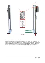
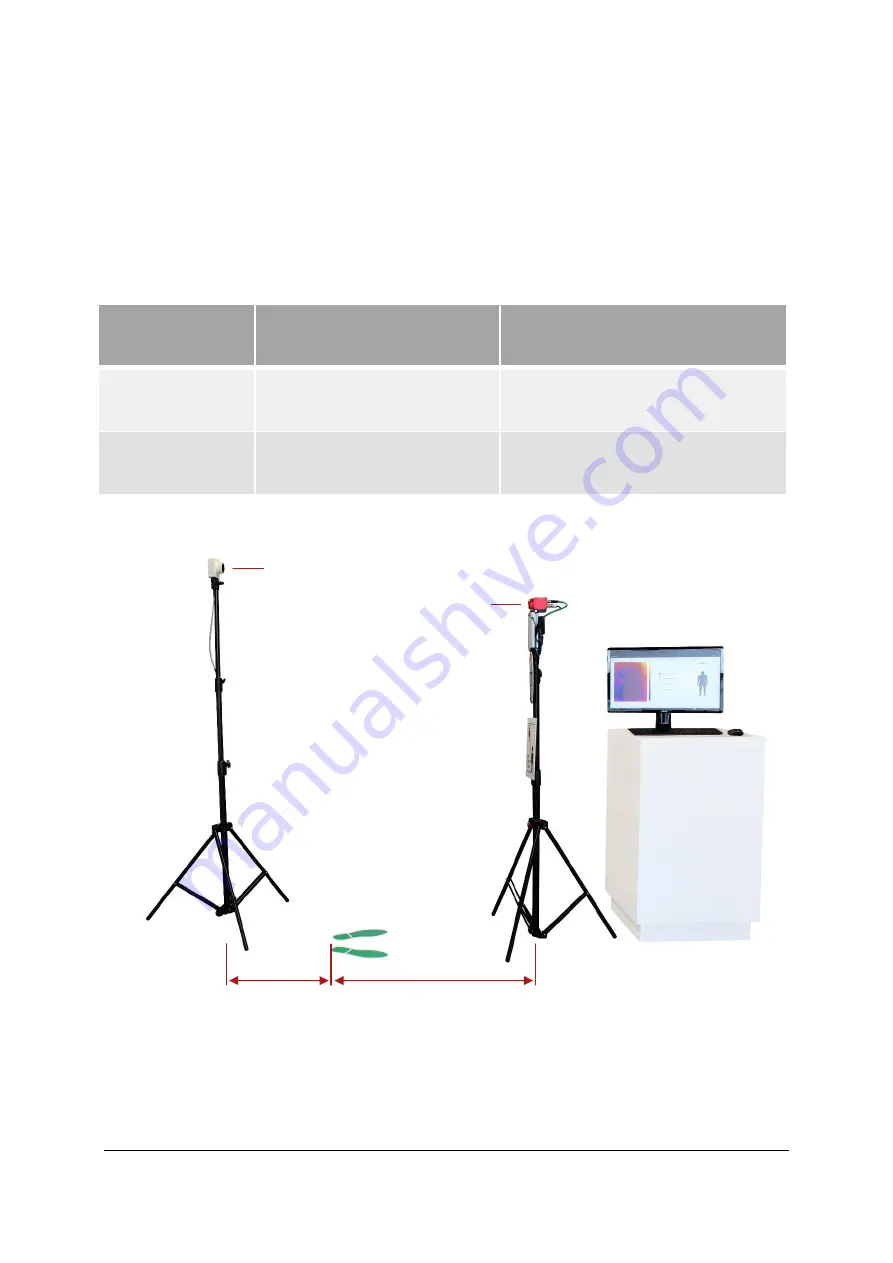
Place the two tripods so that the lens of the camera and the blackbody lens are facing
each other. Now determine the distances between the individual components using a
suitable measuring device. The two following illustrations clearly show how the tripods
and individual components should be positioned in relation to each other.
Please note that depending on the camera version you have purchased, the distance
between camera and user must be varied to cover a comparable range. The following
table shows the distance between camera and user.
Camera version
Distance
Camera / Floor stickers
Distance
Camera / User
IRSX – I336S-7.5
IRSX - I640S-13
1000mm
850mm
IRSX – I336S-13
IRSX - I640S-25
2000mm
1700mm
In a further step, look at the system from the view of the blackbody to the camera and
adjust the distances accordingly.
Distance to the ground. Measured
in each case centrally to the lens
of the camera and the lens of the
blackbody.
Blackbody:
1950mm
Camera:
1650mm
200mm
1000mm
oder
2000mm
Summary of Contents for FebriScan
Page 1: ...April 28th 2020 Page 1 of 49 AT Automation Technology GmbH FebriScan USER GUIDE...
Page 10: ...April 28th 2020 Page 10 of 49 Wing screw Central fixing screw...
Page 12: ...April 28th 2020 Page 12 of 49 320mm...
Page 42: ...April 28th 2020 Page 42 of 49 Appendix Technichal Documentation Blackbody...
Page 43: ...April 28th 2020 Page 43 of 49 Control electronics Blackbody...


