April 28
th
, 2020
Page 20 of 49
I.
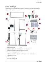
Calibration certificates for camera and blackbody
J.
Power supply unit for monitor
K.
Butt connector set
L.
Installation tool
M.
Monitor with holder and stand
System Setup
The system setup is divided into 3 steps. We recommend doing the installation with 2 or 3
persons.
Step 1: Mounting frame and upper side panels
Position the two upper side parts in such a way that the lens of the black body and the
lens of the camera are facing each other. Insert the screwed-in universal connectors at
the upper profile ends of the side parts - namely into the grooves of the mounting frame's
cross profiles. The profiles are correctly positioned when the outer edges of the
assemblies are in line. Using the installation tool, fix the screws of the universal connector
through the holes in the outer corners of the mounting frame.
Summary of Contents for FebriScan
Page 1: ...April 28th 2020 Page 1 of 49 AT Automation Technology GmbH FebriScan USER GUIDE...
Page 10: ...April 28th 2020 Page 10 of 49 Wing screw Central fixing screw...
Page 12: ...April 28th 2020 Page 12 of 49 320mm...
Page 42: ...April 28th 2020 Page 42 of 49 Appendix Technichal Documentation Blackbody...
Page 43: ...April 28th 2020 Page 43 of 49 Control electronics Blackbody...


