U
nd
er
st
an
di
ng
U
nd
er
st
an
di
ng
th
e
F
ea
tu
re
s
th
e
F
ea
tu
re
s
3--18
Installation and Specifications
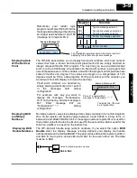
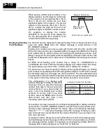
The figure below demonstrates how the Internal Control Relays are mapped to the
OP-panel control register. Notice the sixteen bits in the Internal Control Relays
C200--C217 are loaded into the control register. These control relays function as
outputs for the Lights.
Mapping the Control Register
R432/R433
R20/R21
M+13
M+13
Control register
C374
R200
R432
DSTR
DOUT
ON
OP-panel
Register
Internal
Control
Relays
Not
C374 (always ON after
first scan) maps Control
Relays R20/R21 to OP
registers R432/R433.
OP--640
M+13
12
13
14
15
8
9
10
11
4
5
6
7
0
1
2
3
C216
C210
C200
PLC Program User Memory
LF2
LF3
BD
L1
L2
L3
LF1
LF2
LF3
BD
L1
L2
L3
LF1
C215
C212
C201
C202
C204
C206
C203
C205
C207
C211
C213
C214
C217
Note that
DSTR and
DOUT are
16-bit
instructions.
Mapping the Control
Register

