CLK-1
1-800-633-0405
CLICK Module Insert
www.automationdirect.com/click-plc
3505 HUTCHINSON ROAD
CUMMING, GA 30040-5860
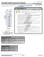
C0-08SIM CLICK Expansion I/O Module
Copyright© 2020,
Automationdirect.com
Incorporated/All Rights Reserved Worldwide
Please read and understand the information in this
insert prior to installation, operation, or servicing
this equipment. Please refer to the CLICK User
Manual (C0-USER-M) for more information
(https://
cdn.automationdirect.com/static/manuals/
WARNING
• Don’t use this equipment in a flammable or explosive environment in order to avoid accidental injury or fire.
• You should use external electromechanical devices that are independent of the PLC (Programmable Logic
Controller) system to provide protection for any part of the system. Otherwise, malfunction or output
failures may result in a hazardous accident.
• When using this product, connect it to the Click CPU unit.
• Please ensure that you earth the Ground terminal of the Power Units for CLICK CPU (C0-00AC/01AC) to
avoid electric shock or equipment damage during a short circuit.
• Don’t operate the equipment with a nonconforming external power supply to avoid electric shock,
equipment damage or fire.
• Don’t intentionally fault wiring, as this may result in equipment damage or fire.
• To avoid electric shock or malfunctions that might result in an accident, don’t touch any terminal while the
PLC power is on.
• Don’t put metals (e.g. Screwdriver) into radiator holes, drop trash or foreign objects (e.g. wire cut-offs) into
the device, in order to avoid electric shock or equipment damage.
• If the equipment is used in a manner not specified by the manufacturer, the protection provided by the
equipment may be invalidated.
CAUTION
• Use and store the equipment in an environment described in the specifications (regarding temperature,
humidity, vibrations, shock, etc.) in order to avoid equipment damage or fire.
• Ensure all wiring has strain reliefs in order to avoid damage to insulation which might result in electric shock
or fire.
• Ensure secondary external power circuits are only live after PLC control program is started. Otherwise a
malfunction or output failure may result in a hazardous accident.
• Don’t block the radiator holes. This may cause an increase of internal temperature resulting in equipment
damage or fire.
• Don’t disassemble or modify the equipment so as to avoid electric shock, equipment damage, or fire.
• Cut off all phases of the external power source prior to performing maintenance work, thus avoiding electric
shock or equipment damage.
General Safety
Please follow the instructions below for personal and operational safety.
In this Insert Sheet, the safety instruction levels are classified into
“WARNING”
and
“CAUTION”
Assumes that incorrect handling may cause hazardous conditions, resulting in
severe injury or death.
Assumes that incorrect handling may cause hazardous conditions, resulting in
medium or slight injury, or may cause equipment damage.
WARNING
CAUTION
General Specifications
+
Operating Temperature
32° to 131°F (0° to 55°C)
Storage Temperature
-4° to 158°F (-20° to 70°C)
Relative Humidity
30% to 95% (non-condensing)
Environmental Air
No corrosive gases permitted (Level 2 environmental pollution)
Agency Approvals
UL61010-2-201
CE (EN61131-2):2007*;
RoHS (2011/65/EU) and amendment (EU) 2015/863
+ Keep out iron powder, moisture, oil or chemicals. Isolate from shock or vibration, direct sunlight, and from electric or ferromagnetic field.
*
Meets EMC and Safety requirements. See the Declaration of Compliance for details.
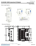
The C0-08SIM unit toggle switch can get hot
when mounted in a hot environment. Wear
appropriate personal safety equipment before
use, to avoid possible burns.
CAUTION
Input Specifications
Inputs per Module
8 Toggle switches
OFF to ON Response
Max. 140ms, Typ. 90ms
ON to OFF Response
Max. 110ms, Typ. 60ms
Status Indicators
Logic Side (8 points, green LED)
Power Indicator (green LED)
Bus Power required
Max. 50mA (All points ON)
C0-08SIM


