DL205 Analog Manual, 7th Edition Rev. D
7-8
Chapter 7: F2-04THM, 4-Channel Thermocouple Input
1
2
3
4
5
6
7
8
9
10
11
12
13
14
15
B
C
D
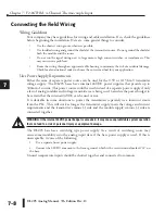
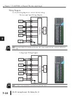
Connecting the Field Wiring
Wiring Guidelines
Your company may have guidelines for wiring and cable installation. If so, check the guidelines
before beginning the installation. Here are some general things to consider:
•
Use the shortest wiring route whenever possible.
•
Use shielded wiring and ground the shield at the transmitter source. Do not ground the shield at
both the module and the source.
•
Do not run the signal wiring next to large motors, high current switches, or transformers. This
may cause noise problems.
•
Route the wiring through an approved cable housing to minimize the risk of accidental damage.
Check local and national codes to choose the correct method for your application.
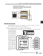
User Power Supply Requirements
Either the same or separate power source can be used for the 0-5V or 0-156 mV transmitter
voltage supply. The DL205 bases have internal 24VDC power supplies that provide up to
300mA of current. This power source could be used instead of a separate power supply if only
a few of analog modules and voltage transmitters are being used. Calculate the power budget to
be certain that the internal 24VDC can be used or not.
It is desirable in some situations to power the transmitters separately in a location remote
from the PLC. This will work as long as the transmitter supply meets the voltage and current
requirements and the transmitter’s minus (-) side and the module supply’s minus (-) side are
connected together.
WARNING: If the internal 24VDC power budget is exceeded, it may cause unpredictable system operation
that can lead to a risk of personal injury or equipment damage.
The DL205 base has a switching type power supply. As a result of switching, noise may
cause some instability into the analog input data if the base power supply is used. If this is
unacceptable, try one of the following:
1. Use a separate linear power supply.
2. Connect the 24VDC common to the frame ground, which is the screw terminal marked ”G” on
the base.
Unused temperature inputs should be shorted together and connected to common.
1
2
3
4
5
6
7
8
9
10
11
12
13
14
15
b
C
D
Summary of Contents for DL205
Page 1: ...DL205 Analog I O Manual Manual Number D2 ANLG M ...
Page 2: ...Notes ...
Page 6: ...Notes ...

