DL205 Analog Manual, 7th Edition Rev. D
7-9
Chapter 7: F2-04THM, 4-Channel Thermocouple Input
1
2
3
4
5
6
7
8
9
10
11
12
13
14
15
B
C
D
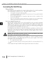
Thermocouples
Use shielded thermocouples whenever possible to minimize the presence of noise on the
thermocouple wire. Ground the shield wire at one end only. For grounded thermocouples,
connect the shield at the sensor end. For ungrounded thermocouples, connect the shield to
the 0V (common) terminal.
Grounded Thermocouple Assembly
A grounded thermocouple provides better response time than an ungrounded thermocouple
because the tip of the thermocouple junction is in direct contact with the protective case.
Ungrounded Thermocouple Assembly
An ungrounded thermocouple is electrically isolated from the protective case. If the case
is electrically grounded it provides a low-impedance path for electrical noise to travel. The
ungrounded thermocouple provides a more stable and accurate measurement in a noisy
environment.
Exposed Grounded Thermocouple
The thermocouple does not have a protective case and is directly connected to a device with a
higher potential. Grounding the thermocouple assures that the thermocouple remains within
the common mode specifications. Because a thermocouple is essentially a wire, it provides a
low-impedance path for electrical noise. The noise filter has a response of >100dB @ 50/60
Hz.
WARNING: A thermocouple can become shorted to a high voltage potential. Because common terminals
are internally connected together, whatever voltage potential exists on one thermocouple will exist on
the other channels.
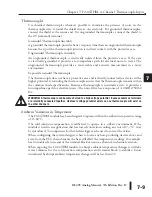
Ambient Variations in Temperature
The F2-04THM module has been designed to operate within the ambient temperature range
of 0°–60°C.
The cold junction compensation is calibrated to operate in a still-air environment. If the
module is used in an application that has forced convection cooling, an error of 2°–3°C may
be introduced. To compensate for this, ladder logic can be used to correct the values.
When configuring the system design it is best to locate any heat-producing devices above and
away from the PLC chassis because the heat will affect the temperature readings. For example,
heat introduced at one end of the terminal block can cause a channel-to-channel variation.
When exposing the F2-04THM module to abrupt ambient temperature changes it will take
several minutes for the cold junction compensation and terminal block to stabilize. Errors
introduced by abrupt ambient temperature changes will be less than 4°C.
1
2
3
4
5
6
7
8
9
10
11
12
13
14
15
b
C
D
Summary of Contents for DL205
Page 1: ...DL205 Analog I O Manual Manual Number D2 ANLG M ...
Page 2: ...Notes ...
Page 6: ...Notes ...

