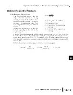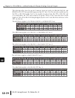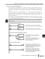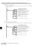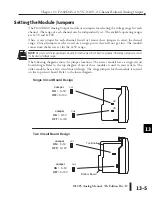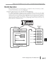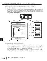
DL205 Analog Manual, 7th Edition Rev. D
13-6
Chapter 13: F2-02DAS-2, 0-5V, 0-10V, 2-Channel Isolated Analog Output
1
2
3
4
5
6
7
8
9
10
11
12
13
14
A
b
C
D
Connecting the Field Wiring
Wiring Guidelines
Your company may have guidelines for wiring and cable installation. If so, check the guidelines
before beginning the installation. Here are some general things to consider:
•
Use the shortest wiring route whenever possible.
•
Use shielded wiring and ground the shield at the transmitter source. Do not ground the shield at
both the module and the source.
•
Do not run the signal wiring next to large motors, high current switches, or transformers. This
may cause noise problems.
•
Route the wiring through an approved cable housing to minimize the risk of accidental damage.
Check local and national codes to choose the correct method for your application.
Transmitter Power Supply Requirements
The F2-02DAS-2 requires a separate transmitter power supply. Each channel requires
21.6–26.4 VDC, at 60mA per channel.
WARNING: If the internal 24VDC base power is used, be sure to calculate the power budget. Exceeding
the power budget can cause unpredictable system operation that can lead to a risk of personal injury or
equipment damage.
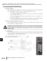
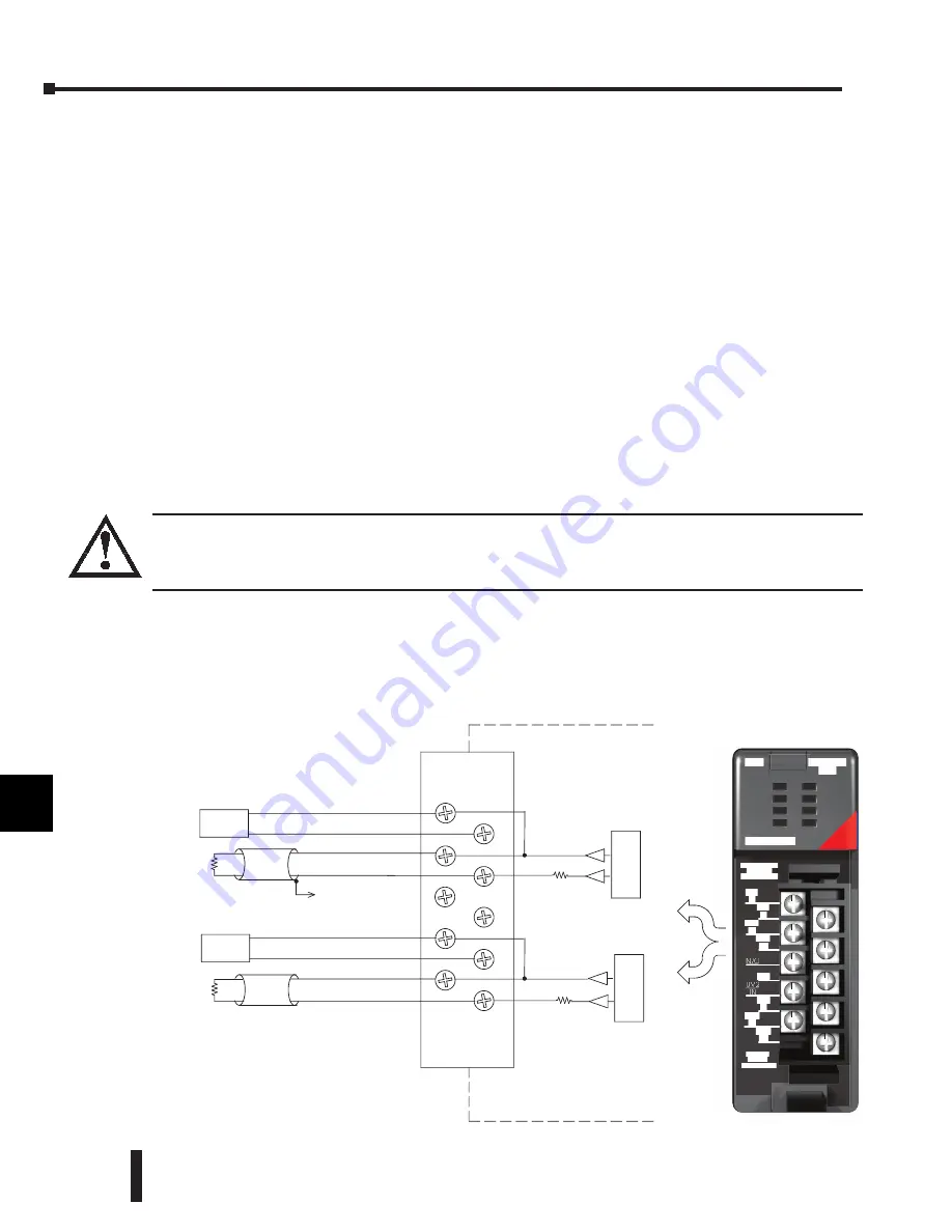
Wiring Diagram
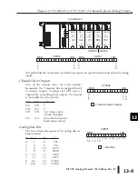
The F2-02DAS-2 module has a removable connector which helps to simplify wiring. Squeeze
the top and bottom retaining clips and gently pull the connector from the module. Use the
following diagram to connect the field wiring.
Internal
Module
Wiring
+
-
Transmitter
See
0V1
+V1
0V2
+V2
NOTE 1
N/C
N/C
Ch 1 load
NOTE 2
Supply
24 VDC
Ch 2 load
NOTE 2
D/A
Voltage Source
D/A
+
-
Transmitter
Supply
VDC
24
Voltage Source
100
100
CH1-V
CH1+V
CH2+V
CH2-V
+V1
IN
CH1
+V
N/C
+V2
IN
CH2
+V
0V1
IN
CH1
-V
CH2
-V
F2-02DAS-2
OUT
ANALOG
2CH
F2-02DAS-2
21.6-26.4 VDC
60 mA CH
ANALOG OUT
0-10VDC
0-5VDC
Ω
Ω
Ω
Ω
NOTE 1: Shields should be connected to the 0V terminal of the module.
NOTE 2: Loads must be within the compliance voltage.
NOTE 3: For non-isolated outputs, connect 0V1 to 0V2.
2K
2K
1
2
3
4
5
6
7
8
9
10
11
12
13
14
A
b
C
D
Summary of Contents for DL205
Page 1: ...DL205 Analog I O Manual Manual Number D2 ANLG M ...
Page 2: ...Notes ...
Page 6: ...Notes ...


