DL205 Analog Manual, 7th Edition Rev. D
16-21
Chapter 16: F2-8AD4DA-2, 8-Ch. In / 4-Ch. Out Analog Voltage Combination
1
2
3
4
5
6
7
8
9
10
11
12
13
14
15
16
C
D
1
2
3
4
5
6
7
8
9
10
11
12
13
14
15
16
C
D
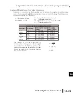
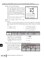
Analog and Digital Input Data Value Conversion
Sometimes it is useful to be able to quickly convert between the signal levels and the digital
values. This is especially helpful during machine startup or troubleshooting. The table provides
formulas to simplify the conversion.
Analog and Digital Input Data Conversion
Resolution Input Range
If the digital value is
known
If the analog
signal is known
12 bit
0–4095
0–5V
A = (D)(5) / 4095
D = (A)(4095) / 5
0–10V
A = (D)(10) / 4095
D = (A)(4095) / 10
14 bit
0–16383
0–5V
A = (D)(5) / 16383
D = (A)(16383) / 5
0–10V
A = (D)(10) / 16383
D = (A)(16383) / 10
16 bit
0–65535
0–5V
A = (D)(5) / 65535
D = (A)(65535) / 5
0–10V
A = (D)(10) / 65535
D = (A)(65535) / 10
• A = Analog value from current transmitter
• A
max
= Maximum analog value
• D = Digital value of input provided to PLC CPU
• D
max
= Maximum digital value
A = (D)(A
max
) / (D
max
)
D = (A)(D
max
) / (A
max
)
D = (A) 65535
10
D = (6) (6553.5)
D = 39321
For example, if a 0–10V range with 16
bit resolution is being used, and the signal
measured is 6V, the formula can be easily
used to determine the digital value (D) that
should be stored in the V-memory location
that contains the data.
Summary of Contents for DL205
Page 1: ...DL205 Analog I O Manual Manual Number D2 ANLG M ...
Page 2: ...Notes ...
Page 6: ...Notes ...

