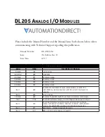
DL205 User Manual, 7th Edition Rev. D
iii
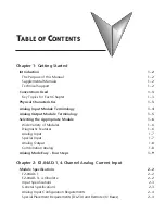
Table of Contents
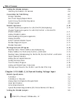
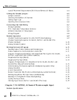
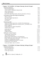
Selecting the Number of Channels
3–5
Selecting the Input Signal Range
3–6
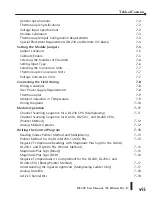
Connecting the Field Wiring
3–7
Wiring Guidelines
3–7
User Power Supply Requirements
3–7
Custom Input Ranges
3–8
Wiring Diagram
3–9
Module Operation
3–10
Channel Scanning Sequence for a DL230 CPU (Multiplexing)
3–10
Channel Scanning Sequence for a DL240, DL250-1 or DL260 CPU
(Pointer method)
3–11
Analog Module Updates
3–11
Understanding the Input Assignments
3–12
Analog Data Bits
3–12
Active Channel Indicator Inputs
3–13
Module Diagnostic and Sign Inputs
3–13
Module Resolution
3–14
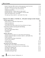
Writing the Control Program
3–15
Reading Values: Pointer Method and Multiplexing
3–15
Pointer Method for the DL240, DL250-1 and DL260 CPUs
3–15
Using Bipolar Ranges (Ptr Method) for the DL240, DL250-1 and DL260 CPUs
3–17
Reading Values (Multiplexing) for the DL230, DL240, DL250-1 and DL260
3–18
Single Channel Selected
3–19
Using Bipolar Ranges (Multiplexing)
3–19
Using 2’s Complement for DL230, DL240, DL250-1, and DL260 CPUs (Multiplex) 3–20
Analog Power Failure Detection
3–21
Scaling the Input Data
3–21
The Conversion Program
3–22
Analog and Digital Value Conversions
3–22
Filtering Input Noise for the DL250-1 and DL260 CPUs Only
3–23
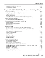
Chapter 4: F2-08AD-1, 8-Ch. Analog Current Input
Module Specifications
4–2
Firmware Requirements
4–2
Analog Input Configuration Requirements
4–2
Input Specifications
4–3
Table of Contents
Summary of Contents for DL205
Page 1: ...DL205 Analog I O Manual Manual Number D2 ANLG M ...
Page 2: ...Notes ...
Page 6: ...Notes ...


