Installing the Panel
10
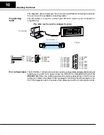
The diagrams shown below give the connector specifications including the pinouts
for each end of the available connecting cables.
The OP-ACBL--1 is used to connect your OP-1212 panel to your computer for
programming.
OP-ACBL--1
This cable must be used to configure the panel.
Computer
Panel
1= not used
2= Dout
3= Din
4= not used
5= 0V
6= not used
7= not used
8= not used
9 = not used
10= not used
11= not used
12= not used
13= not used
14= not used
15= not used
5= 0V
4= not used
3= Dout
2= Din
1= not used
9=not used
8= CTS
7= RTS
6=not used
DB9
DB15
3
3
2
2
5
5
7
8
1
15
1
9
The OP-ACBL--1 (shown above) is also used to connect Allen-Bradley SLC 5/03 and
5/04 PLCs to an OP-1212 panel. Since the OP-1212 is compatible with all of the
Direct
LOGIC PLCs, the cabling requirements will vary depending on the PLC type
being used. Refer to the table on the next page for matching the proper cable to your
PLC. Pin diagrams refer to the ends of the cables and not the communication ports.
Programming
Cable
PLC to Panel Cable


