background image

Installing the Panel

14

Connecting a Power Supply

The OP-1212 panel can operate on DC voltages between 8 and 30 VDC rated at 7

watts. Connect the panel to a power supply (within the required voltage range and

wattage) using the terminal block connector supplied. The connector is polarized to

prevent reversing the connections. The male receptacle on the rear of the panel will

only connect in one way with the female connector that is supplied with your

OP-1212 panel. Pin 1 is the positive connection, while Pin 2 is the negative, or

ground, connection.

You must use an external power supply that

can deliver voltages in the 8 to 30 VDC

range, and can supply 7 watts of power.

Install the female connector to

a cable for attachment to your

power supply.

+

GND

A two-prong male con-

nector is on the rear of

the unit. Your OP-panel is

shipped with the female

connector.

Model

Current Consumed at 12VDC

OP-1212 240mA (all Lamps and LEDs OFF)

570mA (all Lamps and LEDs ON)

120mA (all Lamps and LEDs OFF)

285 mA (all Lamps and LEDs ON)

Current Consumed at 24VDC

NOTE:

Consult our catalog or website, www.automationdirect.com, to purchase a power

supply.

Power Supply

Connections

Summary of Contents for Optimate OP-1212

Page 1: ...OP 1212 Lamp Pushbutton Panel Manual Number OP 1212 M ...

Page 2: ...nt in hazardous environments requiring fail safe performance such as in the operation of nuclear facilities aircraft navigation or communication systems air traffic control direct life support machines or weapons systems in which the failure of the product could lead directly to death personal injury or severe physical or environmental damage HighRiskActivities AutomationDirectspecificallydisclaim...

Page 3: ...eux nécessitant une sécurité absolue par exemple l exploitation d installations nucléaires les systèmes de navigation aérienne ou de communication le contrôle de la circulation aérienne les équipements de survie ou les systèmes d armes pour lesquels la défaillance du produit peut provoquer la mort des blessures corporelles ou de graves dommages matériels ou environnementaux activités à risque élev...

Page 4: ...ude the revision number Title OP 1212 Lamp Pushbutton Panel Manual Number OP 1212 M Issue Date Effective Pages Description of Changes Original 11 96 41 Original Issue Rev A 5 98 10 15 Added cable OP 2CBL 1 Changes per MU OP 001 5 7 97 Rev B 5 2010 All Updated manual to present date ...

Page 5: ...ling the Panel Panel Specifications 7 Physical Specifications 7 Environmental Specifications 7 Operating Specifications 7 Dimensions for Mounting 8 Power and Cabling Requirements 9 What Are Your Application Needs 9 Programming Cable 10 PLC to Panel Cable 10 Choosing the Proper Connecting Cables 12 Connecting a Power Supply 14 Power Supply Connections 14 Connecting the Panel to your Personal Comput...

Page 6: ...DL305 PLCs 25 Using Ladder Logic 25 Using Selected Functions with DirectLOGIC PLCs not DL305 PLCs 26 Using the Remapping Process 26 Using Ladder Logic with DirectLOGIC PLCs 27 Using Ladder Logic with the DL305 29 Using the OP 1212 with an Allen Bradley PLC 31 Using Ladder Logic with Allen Bradley PLC 31 Troubleshooting the OP 1212 Panel Troubleshooting 32 Panel Configuration 32 Panel to PLC Commun...

Page 7: ...1 OP 1212 Pushbutton Panel In This Manual Getting Started Preparing the Labels Installing the Panel Applying Ladder Logic ...

Page 8: ...ns Master panel The software can be used with Allen Bradley PLCs There are several other manuals you will find helpful or necessary D Respective PLC User Manual for the PLC s you are using with the OptiMate panel D OP 9001 M Communications Master User Manual provides details of how to use the OP 9001 for connecting multiple OP Panels to a single CPU D DirectSOFTt User Manual Shows you how to use t...

Page 9: ... Each of the functions for the pushbuttons LEDs and lamps are controlled by the status of their assigned bits within the memory words that you have reserved You interface these words of memory through your ladder logic Prior to connecting the OP 1212 to your PLC load the OP WINEDIT configuration software onto your personal computer and begin to define how you want to use the functions that have be...

Page 10: ...EDIT is ordered as a separate item from the OptiMate panel from AutomationDirect The software is used for both DirectLOGIC and Allen Bradley PLCs After setting a DIP switch on the rear of the panel and attaching the programming cable you are ready to configure your panel The simple and easy to follow screens make configuration a painless process DIP Switch The amount of ladder logic programming kn...

Page 11: ...te a legend transparency There are several ways of doing this A template is provided on the next page that gives you the available dimensions The nicest legends result from using a computer graphics program and a laser printer to create the transparency Bezel Finished Legend Window Frame Insert legend between window frame and cabinet 3 Slide the finished legend into the pocket space between the wi...

Page 12: ...Preparing the Labels 6 Template for Creating Labels 0 60 0 15 0 40 0 20 0 35 3 00 0 10 Dimensions in Inches 0 10 0 15 0 07 3 60 0 60 0 70 3 00 ...

Page 13: ...ating Temperature 0 to 50 C Storage Temperature 20 to 80 C Operating Humidity 5 to 95 non condensing Air Composition No corrosive gases permitted Power Budget Requirement 7 VA 8 30 VDC 570 mA 12 VDC all Lamps and LEDs ON 285 mA 24 VDC all Lamps and LEDs ON Power Connector Removable Terminal Block 2 position Absolute Maximum Voltage 32 VDC Diagnostics Power On CPU Communication Link RS232 or RS422 ...

Page 14: ...Installing the Panel 8 Dimensions for Mounting 8 85 8 40 0 75 Example panel mounting Dimensions in Inches 0 5 1 75 Cutout Area 0 23 0 16 DIA 2 00 3 50 3 50 ...

Page 15: ... feet between the OP 9001 and the last operator interface unit in the chain can be achieved If the distance is 30 feet or less a ribbon cable with easy to install crimp on ribbon connectors can be used OP 9001 Power Supply OP panels DL405 CPU Base Power Source 1 Point to Point A single cable connection from the PLC to the panel gives you access to the PLC s data registers and ladder logic 2 Multi ...

Page 16: ...d 11 not used 12 not used 13 not used 14 not used 15 not used 5 0V 4 not used 3 Dout 2 Din 1 not used 9 not used 8 CTS 7 RTS 6 not used DB9 DB15 3 3 2 2 5 5 7 8 1 15 1 9 The OP ACBL 1 shown above is also used to connect Allen Bradley SLC 5 03 and 5 04 PLCs to an OP 1212 panel Since the OP 1212 is compatible with all of the DirectLOGIC PLCs the cabling requirements will vary depending on the PLC ty...

Page 17: ...sed 21 not used 20 not used 19 not used 18 not used 17 not used 16 not used 15 not used 14 not used 25 not used 24 not used 23 not used 22 not used RJ12 RJ11 RJ12 PLC DB15 4 3 2 3 RJ11 PLC 2 3 2 1 DB15 5 4 DB15 PLC 2 3 2 3 DB15 5 4 RJ12 RJ11 DB15 DB15 DB15 DB15 DB25 DB15 13 14 15 1 7 8 DB25 PLC 2 3 2 3 5 7 4 5 DB15 5 1 1 25 1 15 15 tied 0V 14 tied 0V 13 tied 0V 12 not used 11 not used 10 not used ...

Page 18: ... 1 OptiMate Panel Cables Depending on which PLC you are using you may require as many as two cables one to connect the panel to a personal computer for configuration and one to connect the panel to the PLC Here are the requirements D OP ACBL 1 all units require this cable for configuration This isa 9 pin male to 15 pin male cable that connects your personal computer to the OptiMate unit This cable...

Page 19: ...L 335 37 PPX 335 37 If DCU is used OP 4CBL 2 425 CPU PPX 425 CPU One port 15 pin OP CBL 1 430 CPU PPX 430 CPU Top port 15 pin OP 4CBL 1 TI405t SIMATIC 430 CPU PPX 430 CPU Bottom port 25 pin OP 4CBL 2 SIMATIC TI405t 435 CPU PPX 435 CPU Top port 15 pin OP 4CBL 1 TI405 435 CPU PPX 435 CPU Bottom port 25 pin OP 4CBL 2 Smart Slicet I O panels One port 15 pin OP 4CBL 1 Allen Bradley SLC500 5 03 5 04 Bot...

Page 20: ... the positive connection while Pin 2 is the negative or ground connection You must use an external power supply that can deliver voltages in the 8 to 30 VDC range and can supply 7 watts of power Install the female connector to a cable for attachment to your power supply GND A two prong male con nector is on the rear of the unit Your OP panel is shipped with the female connector Model Current Consu...

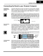
Page 21: ...he left 2 4 8 14 Any address between 0 and 30 is valid for the OptiMate to CPU or to OP9001 communications Address 31 however selects the configuration mode Use this mode when you connect your personal computer to the panel for configuration To select address 31 turn switches 1 through 5 ON NOTE Please note that when the dip switches are changed the OP 1212 must be power cycled before the new sett...

Page 22: ...an be connected directly to the OP 9001 ports or be daisy chained to other OP panels PLC Power Supply Power supply recep tacle Same as the one on the OP 1212 See Page 12 DB15 for connecting to the PLC See chart on Page 11 for selec tion of the proper cable Two DB15 ports for RS422 connection to any OP panel Belden 9279 Specifications No twisted pairs Nom Impedance ohms 2 100 Nom Capacitance pF m 4...

Page 23: ...cator Lamp Flash 1 2 3 4 5 6 7 8 9 10 11 12 1 2 3 4 5 6 7 8 9 10 11 12 1 2 3 4 5 6 7 8 9 10 11 12 1 2 3 4 5 6 7 8 9 10 11 12 1 2 3 4 5 6 7 8 9 10 11 12 Button LEDs ON OFF Button LEDs Flash Button ON OFF Force Data Comm M3 M2 M1 Indicator Lamp LSB MSB m 0 m 1 m 2 m 3 m 4 m 5 The 12 pushbuttons on the OP 1212 panel provide a means of control for any process connected to your PLC The pushbuttons can ...

Page 24: ... starts a process and you want to turn it off after the process has completed Pressing the pushbutton would start the process turns the pushbutton ON and the ladder logic would turn the pushbutton OFF after the process was complete Since the pushbuttons must be configured as maintained alternate for the force function to work the process would be halted until the pushbutton was activated again The...

Page 25: ...s are numbered left to right starting in the upper left corner of their respective area Mapped Memory Location Function m 0 such as V40600 C0 C17 m 1 such as V40601 C20 C37 m 2 such as V40602 C40 C57 m 3 such as V40603 C60 C77 Indicator Lamps ON OFF Indicator Lamps Flash Control Button LEDs ON OFF Button LEDs Flash Control Button ON OFF Status Force Pushbuttons Data Comnd m 4 such as V40604 C100 C...

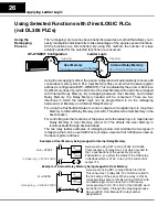
Page 26: ...lash R21 V40602 V40603 V40604 V40605 Button LEDs ON OFF Button LEDs Flash Button ON OFF Force Data Comm R22 R24 R26 R23 R25 R27 R31 R30 bit Indicator Lamp ON OFF Indicator Lamp Flash Button LEDs ON OFF Button LEDs Flash Button ON OFF Force Data Comm 12 11 10 9 8 7 6 5 4 3 2 1 12 11 10 9 8 7 6 5 4 3 2 1 12 11 10 9 8 7 6 5 4 3 2 1 12 11 10 9 8 7 6 5 4 3 2 1 12 11 10 9 8 7 6 5 4 3 2 1 12 11 10 9 8 7 ...

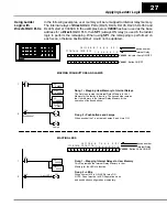
Page 27: ... 10 9 8 7 6 5 4 3 2 1 12 11 10 9 8 7 6 5 4 3 2 1 12 11 10 9 8 7 6 5 4 3 2 1 12 11 10 9 8 7 6 5 4 3 2 1 M1M2M3 12 11 10 9 8 7 6 5 4 3 2 1 12 11 10 9 8 7 6 5 4 3 2 1 12 11 10 9 8 7 6 5 4 3 2 1 12 11 10 9 8 7 6 5 4 3 2 1 12 11 10 9 8 7 6 5 4 3 2 1 12 11 10 9 8 7 6 5 4 3 2 1 M1M2M3 After the address has been selected and mapped it will allow the ladder logic to treat pushbuttons as contacts and Lamps ...

Page 28: ...n with OP WINEDIT by mapping directly to the control relay reserved memory area Only use this method if all of the functions are going to be used in the panel otherwise it will consume internal relays unnecessarily Using this method automatically consumes 96 internal relays In the example below one of the mapped pushbuttons is used to control the output Y12 Refer to Pages 24 25 Y12 C103 Pushbutton...

Page 29: ...on LEDs Flash Button ON OFF Force Data Comm 5 1 2 3 4 5 6 7 8 Rung 1 Pushbuttons and Lamps When pushbutton 7 is activated Lamps 3 and 4 turn ON Rung 2 LEDs When contact X12 is ON LED 9 turns ON NOTE Panel must be in LED Separation mode and pushbutton configured as momentary Rungs 3 and 4 Flashing Lamps To flash a Lamp it must first be turned ON When contact X13 is activated Lamp 5 will turn ON and...

Page 30: ...10 C133 X16 OUT OUT Pushbutton 12 ON Start Process Process Finished Pushbutton 12 OFF C135 OUT V40600 0 1 2 3 4 5 6 7 Internal Relay Indicator Lamp ON OFF V40601 Indicator Lamp Flash V40602 V40603 V40604 V40605 Button LEDs ON OFF Button LEDs Flash Button ON OFF Force Data Comm 1 2 3 4 5 6 7 8 Rung 1 Pushbuttons and Lamps When pushbutton 7 is activated Lamps 3 and 4 turn ON Rung 2 LEDs When contact...

Page 31: ...OUT Pushbutton 12 ON Start Process Process Finished Pushbutton 12 OFF C315 OUT Indicator Lamp ON OFF Indicator Lamp Flash Button LEDs ON OFF Button LEDs Flash Button ON OFF Force Data Comm 1 2 3 4 5 6 7 8 R16 internal relay 1 2 3 4 5 6 7 8 9 10 11 12 device number 0 1 2 3 4 5 6 7 R20 R22 R24 R26 R30 Rung 1 Pushbuttons and Lamps When pushbutton 7 is activated Lamps 3 and 4 turn ON Rung 2 LEDs When ...

Page 32: ...ry to Internal Relay Memory arrow B This affects the User Memory in the m 4 location For controlling all other functions of the panel write the ladder logic to map Internal Relay Memory to User Memory arrow C This affects the User Memory in locations m 0 through m 3 and m 5 The two relay ladder examples of remapping below demonstrate the two types of remapping that can be used with this technique ...

Page 33: ...ton 7 OUT OUT Lamp 4 Lamp 3 X12 Light LED 9 OUT C50 1 2 1 2 SP1 V2004 V40601 LD OUT V2000 V40600 LD OUT Rung 1 Mapping User Memory to Internal Relays The first steps remap the Internal Relay Memory to User Memory for the lamps to function The second step remaps the User Memory to the Internal Relay Memory for the operation of the pushbuttons SP1 V2002 V40602 LD OUT Rung 1 Mapping Internal Relays t...

Page 34: ...FF C75 OUT 1 2 2 3 SP1 V2001 V40601 LD OUT V2000 V40600 LD OUT Rung 1 Mapping Internal Relays to User Memory This step remaps the Internal Relay Memory to User Memory for the Lamps and their flashing feature These steps will be the same except for the address location for the LED flash option 3 1 SP1 V2005 V40603 LD OUT V2004 V40602 LD OUT V40600 0 1 2 3 4 5 6 7 Internal Relay Indicator Lamp ON OF...

Page 35: ...r 0 1 2 3 4 5 6 7 R20 Rung 2 Pushbuttons and Lamps When pushbutton 7 is activated Lamps 3 and 4 turn ON Rung 2 LEDs When contact IO12 is ON LED 9 turns ON NOTE Panel must be in LED Separation mode and pushbutton configured as momentary 0 1 2 3 4 5 6 7 R17 R21 C374 R400 R16 DSTR DOUT R410 R20 DSTR DOUT Rung 1 Mapping User Memory to Internal Relays The first steps remap the Internal Relay Memory to ...

Page 36: ...re the same for the LED flash option with the exception of the internal relay number NOTE Panel must be in LED Separation mode and pushbutton configured as momentary Rung 1 Mapping Internal Relays to User Memory This step remaps the Internal Relay Memory to User Memory for the Lamps and their flashing feature These steps will be the same except for the address location for the LED flash option C37...

Page 37: ...Separation is disabled and the pushbutton is configured as maintained Rung 2 LEDs When contact I 0 3 is ON LED 9 turns ON NOTE Panel must be in LED Separation mode and pushbutton configured as momentary Rungs 3 and 4 Flashing Lamps To flash a Lamp it must be first turned ON When contact I 0 1 is activated Lamp 5 will turn ON and when contact I 0 2 is activated the Lamp will flash Rungs 5 and 6 Fla...

Page 38: ...ownload the configuration the message could not communicate with panel appears D Examine the two LEDs on the rear of the panel that show the state of the communication link If the RX LED blinks but the TX LED does not verify that you are using the appropriate cables D If the RX LED does not blink the communication cable is plugged into the wrong serial port of the PC the cable is faulty or the pan...

Page 39: ... N7 7 When I press a pushbutton nothing happens D Verify that the control relays that you are using in your ladder logic match the ones associated with the memory location that you mapped to the panel DirectLOGIC Allen Bradley Mapping Assignments Mapped Memory Location Function m such as V40600 C0 C17 m 1 such as V40601 C20 C37 m 2 such as V40602 C40 C57 m 3 such as V40603 C60 C77 Indicator Lamps ...

Page 40: ... are remapping in the proper direction and that you are using a contact that is always ON as the input to the remapping logic Remapping must be performed every scan to function properly D Verify that LED Separation Mode was enabled during panel configuration When I press a pushbutton the associated LED does not turn ON D If the LED Separation Mode was enabled the LED will work independently of the...

Page 41: ... 633 0405 Support is available Monday through Friday from 9 00 A M to 6 00 P M Eastern Standard Time Our website address is http www automationdirect com All electrical circuits connected to the communications port receptacle are rated as Safety Extra Low Voltage SELV Operating Temperature 0 to 50 C Storage Temperature 20 to 70 C Operating Humidity 95 non condensing Air Composition No corrosive ga...

Page 42: ...1A Worksheets ...

Page 43: ...h Button LED ON OFF Button LED Flash Button Status Force Function 1 C0 C20 C40 C60 C100 C120 2 C1 C21 C41 C61 C101 C121 3 C2 C22 C42 C62 C102 C122 4 C3 C23 C43 C63 C103 C123 5 C4 C24 C44 C64 C104 C124 6 C5 C25 C45 C65 C105 C125 7 C6 C26 C46 C66 C106 C126 8 C7 C27 C47 C67 C107 C127 9 C10 C30 C50 C70 C110 C130 10 C11 C31 C51 C71 C111 C131 11 C12 C32 C52 C72 C112 C132 12 C13 C33 C53 C73 C113 C133 M3 ...

Page 44: ...N7 1 2 N7 2 2 N7 3 2 N7 4 2 N7 5 2 4 N7 0 3 N7 1 3 N7 2 3 N7 3 3 N7 4 3 N7 5 3 5 N7 0 4 N7 1 4 N7 2 4 N7 3 4 N7 4 4 N7 5 4 6 N7 0 5 N7 1 5 N7 2 5 N7 3 5 N7 4 5 N7 5 5 7 N7 0 6 N7 1 6 N7 2 6 N7 3 6 N7 4 6 N7 5 6 8 N7 0 7 N7 1 7 N7 2 7 N7 3 7 N7 4 7 N7 5 7 9 N7 0 8 N7 1 8 N7 2 8 N7 3 8 N7 4 8 N7 5 8 10 N7 0 9 N7 1 9 N7 2 9 N7 3 9 N7 4 9 N7 5 9 11 N7 0 10 N7 1 10 N7 2 10 N7 3 10 N7 4 10 N7 5 10 12 N7...

Page 45: ...________ 10 ______________________________ 5 _______________________________ 11 ______________________________ 6 _______________________________ 12 ______________________________ LED Descriptions 1 _______________________________ 7 _______________________________ 2 _______________________________ 8 _______________________________ 3 _______________________________ 9 _______________________________ ...

Page 46: ...shielded cable 12 13 Communications Master 9 Connector specification 10 Programming cable 10 Connector specifications 12 13 PLC to Panel cable 10 Control relays 24 25 27 29 Cutout area for panel 8 D DCM 12 13 DCU 12 13 Dimensions for mounting 8 DirectSOFT 2 G GE Series 1 12 13 I Internal Relays 22 L Labels 5 Preparing labels 5 Template 5 Legend 5 M Memory mapping 17 N NEMA 7 ...

Page 47: ...16 OP CMCON 1 12 13 OP CMCON 2 12 13 P Power supply 14 Product support 17 18 R Remapping 22 26 Ribbon cable 9 RS422 16 S SIMATIC 12 13 SLC500 12 13 5 03 12 13 Slice I O 12 13 Specifications 7 T Termination resistor 15 TI305 12 13 TI405 12 13 ...

Reviews: