background image

DPM3-E Electrical User Manual, 1st Edition

User Manual - DPM3-E Series Electrical Panel Meters

11

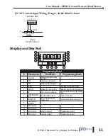
DC/AC Current Input Wiring (Ranges: 50/60/100mV shunt)


Terminals CN2

1 2 3 4 5

I

SHUNT

N

L

Shunt

50/ 60/ 100 mV

Display and Key Pad


PROG

MIN

MAX

TRMS

1

2

3

4

ENTER

DATA

MAX/MIN

MICRA

4

1

2

3

5

6

7

8

9

10

11

12

13

Programming Panel

#

Description

Run Mode

Programming Mode

1

True RMS

Indicates reading AC using 

true RMS

---

2

MAX

Indicates peak displayed

---

3

MIN

Indicates valley displayed

---

4

PROG

---

Indicates programming mode

5

DISPLAY

Displays the input variable

Displays programming parameters

6

UP

Direct access to setpoints

Increments the value of the flashing 

digit

7

SHIFT/MAX/MIN 

KEY

Recalls Max/Min values

Moves to the right

8

ENTER KEY

Enters in PROG mode. 

Displays data

Accepts data. Advances program

9

Free space for 

units label

---

10

LED Output 4

---

---

11

LED Output 3

---

---

12

LED Output 2

Activaton Output 2

Programming output 2

13

LED Output 1

Activation Output 1

Programming output 1

Summary of Contents for ProSense DPM3-E Series

Page 1: ...ProSense DPM3 E Series Digital Panel Meter for true rms ac or dc voltage and amperage electrical input signals Models User Manual DPM3 E H DPM3 E L DPM3 E A2R H DPM3 E A2R L TRMS TRMS...

Page 2: ...7 Installation 7 Wiring Terminals 8 Wiring Examples 10 DC AC Voltage Input Wiring Ranges 2 20 200 600 V 10 DC AC Current Input Wiring Ranges 1A 5A 10 DC AC Current Input Wiring Range 200mA 10 DC AC C...

Page 3: ...17 Logic functions 17 Logic functions menu 18 Table of programmable functions 19 Configuration Lock Out 20 Lock out menu diagram 21 Lock out menu diagram continued 22 Output Options 23 Relay Configur...

Page 4: ...pean legislation regarding waste of electrical and electronic equipment from products put on the market after August 13 2005 the user can give it back without any cost to the place where it was acquir...

Page 5: ...manuals the best in the industry We rely on your feedback to let us know if we are reaching our goal If you cannot find the solution to your particular application or if for any reason you need techn...

Page 6: ...n parameters can be totally or selectively locked out to prevent unauthorized or accidental changes to the meter s operation Other features include memory and reset of minimum valley and maximum peak...

Page 7: ...g the unit in place put the fixing clips on both sides of the case and slide them through the guide tracks until they reach the panel at the rear side Press slightly to fasten the clips to the latchin...

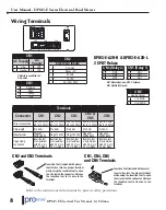
Page 8: ...2 3 4 1 2 3 4 5 6 CN4 CN5 CN6 1 2 CN2 Electrical Inputs 1 Common 2 Shunt 2V 3 200mA 4 1A 5A 5 20 200 600V CN3 1 Common 2 Peak 3 Valley 4 Hold Polarity insensitive for DC power CN1 AC Supply DC Supply...

Page 9: ...ts CAUTION The isolation rating of the input common of the meter with respect to the option card common and to the Logical Functions common if used is 250 Vrms and 500 Vrms with respect to AC Power te...

Page 10: ...es 1A 5A Terminals CN2 1 2 3 4 5 I N L 1 5 A DC AC DC AC Direct Connection Connection using and AC Current Transformer Terminals CN2 1 2 3 4 5 I N L 1A 5A AC MAX R1 R2 Important When using a current t...

Page 11: ...reading AC using true RMS 2 MAX Indicates peak displayed 3 MIN Indicates valley displayed 4 PROG Indicates programming mode 5 DISPLAY Displays the input variable Displays programming parameters 6 UP D...

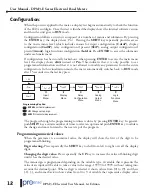
Page 12: ...s visualization mode the meter automatically switches back to RUN mode after 15 seconds sine the last key press 1 Input Menu 2 3 4 5 Display Menu Relay Configuration Menu Analog Output Menu Logic Func...

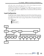
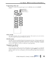
Page 13: ...configuration data is stored in memory The meter will then return to RUN mode Input Configuration The figure below shows the input configuration menu Divided into four submenus each one of them separ...

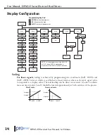
Page 14: ...ximum in both ScAL and tEAcH methods ENTER Vertical displacement UP Changes active digit SHIFT Horizontal displacement Programming Key Pad Scaling For linear signals scaling is achieved by programming...

Page 15: ...ts of the process is known tEACH method The input values are introduced directly from actual electrical values The input signal device must be connected to the meter and operational when each point is...

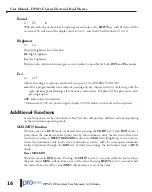
Page 16: ...ivates the function Measured at 230V AC power supply display 100 00 amber colour and with no options Additional Functions Several functions can be controlled via Key Pad that will produce different ac...

Page 17: ...en stored in the non volatile memory of the meter Factory configuration INPUT 600V DC DISPLAY Input 1 0000 0 Display 1 0000 0 Input 2 600 0 Display 2 600 0 Filter P 0 Round 01 Brightness High DISPLAY...

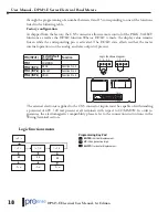
Page 18: ...meter internal operation nor the analog and relay outputs if present Logic functions diagram 1 2 3 4 1 2 3 4 CN3 1 2 3 4 PIN INPUT Factor Default Functions Function PIN 1 COMMON PIN 2 INP 1 PEAK Funct...

Page 19: ...he peak value MAX Low level 4 VALLEY Displays the valley value MIN Low level 5 RESET PEAK VALLEY Perform a reset of the peak or the valley depending on which is being displayed Falling edge 6 HOLD Fre...

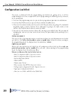
Page 20: ...ecommend changing the code set at factory and to write down your personalised code and keep it in a safe place TOTAL LOCKOUT The access to the programming routines to read data is allowed even if all...

Page 21: ...er will return automatically to the run mode Total lockout programming is achieved by changing the totLC variable to 1 changing it to 0 will lead to the selective lockout of the programming variables...

Page 22: ...M3 E Series Electrical Panel Meters 22 Lock out menu diagram continued 0 allows its programming 1 locks the access to programming Only appear if the corresponding options are present in the meter InPu...

Page 23: ...wing relay operational parameters must also be set a HI LO ACTING MODE In HI mode the output activates when the display value exceeds the setpoint level and in LO mode the output activates when the di...

Page 24: ...git SHIFT Horizontal displacement Programming Key Pad Direct access to the relay setpoints value programming It is possible to directly access the relay setpoint values without the need to go through...

Page 25: ...riety of terminal equipment such as graphic recorders controllers remote displays or other devices that accept input data in analog form The display values producing the full scale output OUT HI and O...

Page 26: ...0 1 mV 60mV 0 1 rdg 0 1 mV 100mV 0 1 rdg 0 1 mV 200mA 0 3 rdg 0 05 mA 1A 0 3 rdg 5mA 5A 0 3 rdg 5mA 50mV 0 3 rdg 0 1 mV 60mV 0 3 rdg 0 1 mV 100mV 0 3 rdg 0 1 mV Accuracy Conditions AC or DC Input 15...

Page 27: ...sing 0 5A 250V DIN 41661 22 53 VAC 50 60 Hz 10 5 70 VDC recommended fusing 2A 250V DIN 41661 Power Consumption 5W without options 8W max Filter Cutoff frequency 4Hz to 0 05Hz Slope 20dB Dec Environmen...

Reviews: