DPM3-E Electrical User Manual, 1st Edition
User Manual - DPM3-E Series Electrical Panel Meters
18
through the programming of a number between 0 and 15 corresponding to one of the functions
listed in the following table.
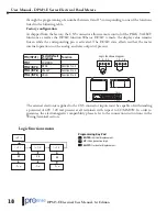
Factory configuration
As shipped from the factory, the CN3 connector allows remote control of the PEAK, VALLEY
functions as well as the HOLD function.When a HOLD is made, the display value remains
frozen while the corresponding pin is activated. The HOLD state affects neither the meter
internal operation nor the analog and relay outputs if present.
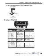
Logic functions diagram
1 2 3 4
1 2 3 4
CN3
1 2 3 4
PIN (INPUT) Factor Default
Functions
Function
PIN 1
COMMON
PIN 2 (INP-1)
PEAK
Function No. 3
PIN 3 (INP-2)
VALLEY
Function No. 4
PIN 4 (INP-3)
HOLD
Function No. 6
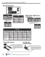
The external electronics applied to the CN3 connector inputs must be capable of withstanding
a potential of 40V / 20 mA present at all terminals with respect to COMMON. In order to
guarantee the electromagnetic compatibility please refer to the connection instructions in the
Wiring Terminal section.
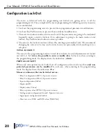
Logic functions menu
-
-
-
-
-
-
-
-
-
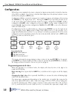
ENTER:
Vertical displacement.
UP:
Changes active digit.
SHIFT:
Horizontal displacement.
Programming Key Pad

