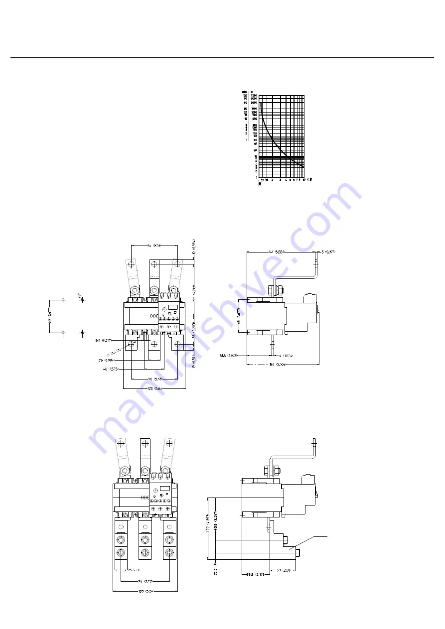
3ph typical tripping characteristics
Current (multiples of setting current)
4.
Manual or automatic reset
Set the adjustment dial.4 (fig.2) in the position of arrow as follows:
M= manual reset by means of pushbutton .4 (fig.2)
A= automatic reset
By operating the pushbutton .4 (fig.2) contact (95-96) closes, if tripped.
Automatic reset is not suggested for permanent contact control devices as,
when the tripping occurs, the motor is automatically reenergized after the
cooling time of the relay.
5.
Function of the red stop pushbutton
Stop button .2 (fig.2) allow to open momentarily the contact (95-96) but it
can't be used to reset the relays when tripped.
6.
Test before commissioning
Press pushbutton .4 (fig.2) to reset relay. Move the actionator .3 (fig.2) in
direction of arrow marked "TEST", the relay trips. NC contact (95-96) opens
and NO contact (97-98) closes. Trip indicator .3 (fig.2) shows yellow for
tripped condition.
7.
Fuse protection
Short circuit protection of the main poles is achieved by a back up fuse as
indicated on rating table.Short circuit protection of auxiliary contacts: 6AgG.
8.
Permissible ambient temperature
-25°C to +55°C temperature compensated.
RTD320 with links for direct connection to
GH15RT, ST, TT contactors
Average values at 20°C ambient
temperature, tripping three-phase from cold
condition. Proceeding from service condition
the times decrease to 20-30% of the
characteristic values.
Fig. 3A
Fig. 3B
RTD320 with links for direct connection to GH15RT, ST, TT
contactors and terminal lugs KAL-4 (optional)
KAL-4
Specifications are subject to change without notice
*
*
The assembly of the links is provided by the customer
Check that the position of the links be the same as those indicated in the drawing
*


