-|Transparent Guide|-
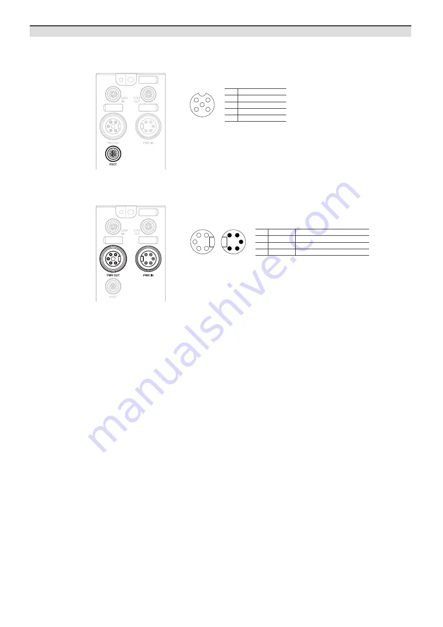
04. Connect the power supply to ADIO
Be sure not to exceed 9 A of the maximum supplying current to the sensor (US).
01. Turn off all power.
02. Connect the 7/8" connector to the power supply port. See the connections below.
1, 2
0 V
Sensor and actuator supply
3
F.G.
Frame ground
4
+24 VDCᜡ
Sensor supply
5
+24 VDCᜡ
Actuator supply
1
2
3
4
5
5
4
3
2
1
PWR OUT
PWR IN
Port Connections
03. Connect with the atIOLink
Do not use the PDCT port and the Ethernet port at the same time.
01. Connect the M12 connector to the PDCT port. See the connections below.
1
4
5
3
2
1
Not Connected (N.C.)
2
Data -
3
0 V
4
Not Connected (N.C.)
5
Data +
02. Connect the connector to the network device.
• Network device: PC/laptop that atIOLink software is installed
03. Put the waterproof cover on the unused port.


