2D-2
Special considerations for the AutoPilot
Combina-
tion
Manifold
Under normal operation, a small amount of gas is introduced
into the pool system by the injector. Plumb the Manifold so that
these bubbles do not interfere with the operation of pool equip-
ment. For example:
1.
Install the manifold after any Pressure Pool Cleaners (such
as a Polaris 360).
2.
Install the manifold after any Tablet/Erosion Feeders that
could collect gas bubbles.
2D-3
. Water Check Valve:
If the pool equipment is mounted
above the water line, a check valve must be installed between
the pump outlet and the Injector Manifold. This will prevent the
pump from draining and losing its prime (when not in use).
2D-4
. Pressure Test:
If a pressure test is required, it should be performed prior to
connecting the Ozone Gas Line. A 3/4” pipe cap is provided
for the pressure test.
2D-5.
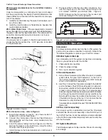
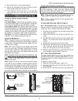
Ozone Gas Line - refer to Figure 2.
1.
Install Tube Adapter on injector. Use thread sealant if
needed. (Do not use thread tape.)
2.
Connect the shorter end of the Ozone Check Valve and
Tube Assembly with the check valve installed onto the
Tube Adapter.
3.
Cut off the excess tubing from the longer end so that the
line from the injector to the CoPilot is as straight and free
from dips and loops as possible.
4. Install Clamps on the Tube Adaptor and on both ends of
Check Valve.
Equipment
Ozone Check Valve
From Pool
Flowmeter
Tube Adapter
and Tube Assembly
to Pool
Return
Lug(s)
Bonding
Indicators
Ozone Power
Flow Control Assembly
(Install after checking flow)
(Preinstalled)
Check Valve
Clamps
3
Figure 2
Installation Diagram
5.
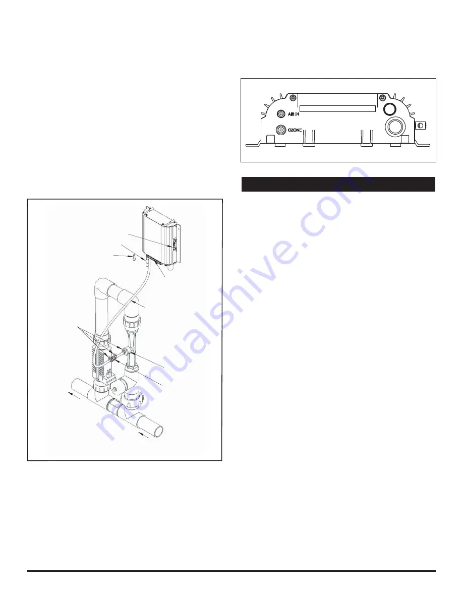
The base of the CoPilot has two tube connections. Con-
nect the longer end of the ozone supply tubing to the
port marked "OZONE" (see Bottom View - Figure 3).
NOTE: Connecting the Ozone Line to the incorrect port
will cause damage to the ozone generator.
SECTION 3
Operation
Operation
3A General
To achieve optimal performance from the CoPilot system, the
pool must be as clean as possible to start with. Refer to the
“Pool Water Preparation” section of your Pool Pilot manual.
3B Initial System Start-Up
Upon completing all of the system connections and cleaning
the pool, you are ready to start the CoPilot.
1.
Check electrical connections.
2
. Check for proper voltage.
3.
Turn on pool circulation system.
3C Normal Operation
1.
Ozone Power
Indicator Lights: When the pool’s circulation
system starts, the green LED indicator(s) on the front of
the CoPilot will illuminate. The COP-A and COP-B should
show 1 and 2 indicators, respectively.
2.
Gas Flow: Connect the Flowmeter provided to the “AIR IN”
port on the base of the CoPilot (see Figure 3). Under worst-
case system conditions the Flowmeter Ball should indicate
at least a small amount of air fl ow. If not, adjust system
valves as required to reduce back pressure and/or increase
fl ow through the manifold. Under nominal conditions, the
Ball should fl oat above the middle of the fl owmeter. It is ok
if the Ball is all the way at the top if it is not stuck. Tap the
Flowmeter to verify that the Ball is not stuck.
If you experience complications see TROUBLESHOOTING
Section 4D.
3D Flow Control Assembly
Once proper suction is established, remove the Flowmeter
and install the Flow Control Assembly on the “AIR IN” port of
the CoPilot. The Flow Control Assembly must remain attached
to the CoPilot, except when temporarily removed to verify fl ow
with the Flowmeter
3E System Shut-Down
The following sequence of steps must be followed for servicing
or for storage.
CoPilot Corona Discharge Ozone Generators
Figure 3
CoPilot Connections


