1.
Disconnect the power to the ozone generator.
2.
After the ozone generator has been shut down, the pool
water circulation pump may be turned off.
3.
If the system is to be shut down for an extended
period, disconnect the Ozone Gas Line from the ozone
generator.
SECTION 4
Maintenance and Service
Maintenance and Service
4A
System Electromechanical Overview
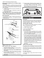
Refer to Figure 4.
4A-1 Ozone Module:
The CoPilot Ozone Generators are con-
structed with High Voltage Corona Discharge Ozone Modules.
The COP-A has one Module, the COP-B has 2 modules.
4A-2
. Indicator Lights:
Each indicator light on the base of the
CoPilot corresponds to an Ozone Module inside the unit. Model
COP-A has one indicator, model COP-B has two. A green light
indicates proper operation of its respective Ozone Module. For
red indicators or no indicators, see Troubleshooting Section.
4A-3
. Fuse:
The CoPilot is equipped with an externally acces-
sible AGC-1 fuse, located on the base of the unit.
4B
System Maintenance
4B-1
.
The green "ozone power” indicator light(s) on the front
of the CoPilot indicate that the ozone power supply is operating
properly. When an indicator light turns red, replace the corre-
sponding ozone module.
4B-2
.
Each ozone module should be replaced after 15,000
hours of operation. Even if the green indicator light(s) are glow-
ing, the ozone module may be producing little or no ozone
after this period of time due to contamination within the corona
discharge ozone chamber.
4B-3.
Regularly reinstall and check the fl owmeter for proper
fl ow.
Always remove the fl owmeter after confi rming proper
fl ow.
Inspect ozone supply tubing for cracks or wear and
replace as necessary.
4B-4
.
Replace the Ozone Check Valve and Tube Assembly
every year or sooner, if needed. If there is evidence of water
leaking past the Check Valve toward the CoPilot shut down the
Ozone Generator Immediately and replace the Ozone Check
Valve and Tubing Assembly. If water entered the CoPilot allow
the unit to dry completely before restarting the unit. Evidence
of water in the CoPilot may void the warranty.
WARNING:
Do NOT touch the ends of the Ozone Check Valve
and Tube Assembly or check valve when replacing. Trace
amounts of nitric acid may be present on the check valve and
could prove harmful if touched or ingested.
4B-5.
While operating, check to see if bubbles are entering
the pool. If MDV is installed, check the MDV for bubbles.
4B-6.
Clean or replace the Flow Control Assembly every
year or sooner if needed.
4C Generator Servicing - Refer to Figure 4
4C-1
. Removing the Cover:
The CoPilot ozone generator
may be serviced on the wall without disconnecting any of the
plumbing or wiring. Simply remove the cover as follows:
1.
Shut down the pool system power, then disconnect power
to the ozone generator.
2.
From the Top End-cap of the CoPilot, remove the 2 rear
screws.
3.
From the Bottom End-cap, remove the 2 front screws. See
Figure 4 - Do not remove the screws securing the unit to
the wall.
4.
Carefully lift and pull the cover off of the CoPilot.
5.
Hold the cover and locate the screw connecting the ground
wire to the base. Remove the screw and set the cover
aside. Do not hang the cover from the ground wire.
6.
The Base will remain fi rmly mounted to the wall with the
Ozone Modules fully accessible for servicing.
4C-2.
Ozone Module Replacement
The green indicator lights on the front of the CoPilot corre-
spond from left to right to Ozone Module numbers 1 and 2.
The ozone modules are numbered beginning with number 1
at the bottom.
To replace an ozone module:
1.
Open the CoPilot as described in section 4C-1.
2.
Disconnect the tubing at both the inlet and outlet of the
ozone electrode.
3.
Remove the two nuts that secure the ozone electrode to
CoPilot Corona Discharge Ozone Generators
4
Top View
Top Endcap-
Remove back
screws only
Remove
Cover
Bottom View
Bottom Endcap-
Remove front
screws only
Ozone
Power Supply
Module #1
Module #2
Ozone
Fuseholder
Electrode
Support Nut
Indicators
Electrode
Support Bracket
(Do not remove)
Figure 4
Component Locations (COP-2-B Shown).


