© 2018 Autoslide Pty Ltd
MultiDrive
17
2.
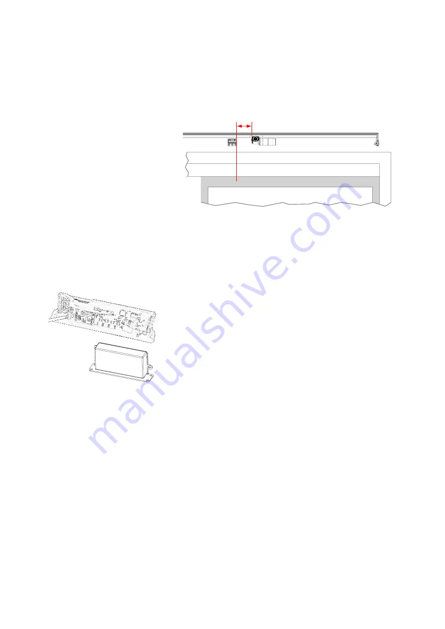
Slide the motor along the base until it is
1.97
”
(50 mm) from
the mark you made on the
door
for the bottom bracket position
(Figure 14 and Figure 17, where
C =
1.97” or 50 mm).
3.
Tighten the slider nuts to hold the motor in place.
Note
: Non-bi-parting doors do
not
use a top bracket.
Figure 17: Right-opening sliding door: motor and bottom
bracket. The right side is shown with the sliding door open.
(f)
Controller and AC adapter
The controller and AC adapter sit next to the motor.
Steps:
1.
Lay the motor cable on the base in between the two tracks.
2.
Slide the controller along the base (over the motor cable) until
it is
1.97
”
(50 mm) from the motor (see Figures to 18 to 20,
depending on the type of door, where
D
=
1.97” or 50 mm).
The slider should be in the track
furthest
from the door.
3.
Slide the AC adapter along the base (over the motor cable)
until it is
1.97
”
(50 mm) from the controller (Figures to 18 to 20
where
D
=
1.97” or 50 mm). The slider should be in the track
furthest
from the door.
4.
If you are installing a mode pad on the door jamb, lay the cable
connected to the mode pad on the base between the two
tracks and
underneath
the AC adapter.
5.
Clip the cable cover (cut it if necessary) over exposed cables
on the base to prevent cables touching the belt.
C


