background image

Notice  

The manufacturer will accept no responsibility for any electrical damage resulting from improper 
installation of the product, be that either damage to the vehicle itself or to the Unit. This Unit must 
be installed by a certified technician using all safety devices supplied. Please note that this guide 
has been written for properly trained Autostart technicians, a certain level of skill and knowledge is 
therefore assumed.  Please review the Installation Guide carefully before beginning any work. 

Warning 

This Unit is designed for vehicles with an 

automatic

Transmission only. Before installing the 

Unit, test that the vehicle does not start when the gear select lever is in the “Drive” position. If it 
starts in gear, install a manual-transmission car starter instead. 

H.3.

1

0.S.3.20

DOC

.1.01

– September 2, 2003 –  CA 

Manufactured in Canada by Autostart

A U T O M A T I C  

T R A N S M I S S I O N   M U L T I -

C H A N N E L   R E M O T E   S T A R T E R   S Y S T E M  

AS-1412

Installation Guide 

Table of Contents 

Introduction ...................................................2
Included in the Package ...............................2

Before You Get 

Started

…........................3

Harness Description .....................................4

6-Pin Main Ignition Harness.....................4
5-Pin Secondary Harness........................5
12-Pin Accessories Harness....................5

Flashing the Hood Pin ..................................8
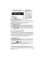
The Programming Assistance Button (a.k.a. 
PAB.) ............................................................9
Before Programming a Transmitter ..............9
How to Program the Transmitter. .................9
How to Enter Programming Options Mode...9
Programming Options.................................10
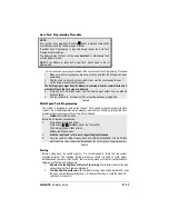
Auto Tach Programming Procedure ...........11
Multi-Speed Tach Programming.................11
Testing ........................................................11

Closing Up ..................................................12
Supplementary Information ........................12
Fifth Relay Output (2nd Ignition or 2nd 
Accessories or 2nd Crank Output) .............12

Ignition-controlled Door Locks...............13
Secure Lock...........................................13
Passive or Active Arming Starter Kill.....13
Lock Pulse Duration ..............................13
Engine Run Time...................................13
Idle Mode...............................................13

Resetting the Module (without the plug-in 
valet)...........................................................13
Resetting the Module (with the use of the 
plug-in valet) ...............................................14
Troubleshooting Poor Transmitting Range 14

Please note: 

Button 

,

 is for the 

LOCK/UNLOCK 

functions. 

Button 

,,

 is for the 

START/STOP 

functions. 

Buttons 

,

 & 

,,

 (together) is for the 

TRUNK 

release function. 

The LED is NOT included in this model. 

Summary of Contents for AS-1412

Page 1: ...T E S T A R T E R S Y S T E M AS 1412 Installation Guide Table of Contents Introduction 2 Included in the Package 2 Before You Get Started 3 Harness Description 4 6 Pin Main Ignition Harness 4 5 Pin S...

Page 2: ...in the box The following is a list of components included in the kit 1 Control Unit 1 2 button Remote Transmitter 1 R 1 Interconnect Cable 1 R 1 Receiver 1 Hood Pin switch 1 6 Pin Main Ignition Harne...

Page 3: ...properly Make sure that all safety equipment is installed the Valet Button if installed the Hood Switch and the warning label When wiring in parallel make sure to isolate each connection with a diode...

Page 4: ...e 12 volts source at the IGNITION switch the 12 Volt wire is too small to supply the necessary current In this case the fuse box or the B connection on the battery is recommended D YELLOW 30 A ignitio...

Page 5: ...ing and therefore it is essential that it is installed 5 YELLOW 12 V Parking Light output This wire provides a 12 V output 15 A max and must be connected to the Parking Light wire that tests 12 V when...

Page 6: ...icle is running triggering this input will activate Idle Mode The External Trigger wire can also be used to operate as a negative trigger with the Trunk Pin switch the Key Sense wire or the Door Pin s...

Page 7: ...set to 30 min if the Glow Plug Light is still on after the delay expires the Module will proceed to start the Engine Also known as the wait to start light The purpose of the Glow plug circuit on dies...

Page 8: ...20 seconds to get into one of the sub menus Failure to do so will result in the Module exiting the Programming Centre and the Installer will have to Flash the Hood Pin once more Remember You can use...

Page 9: ...g Options Mode The System is equipped with two custom Programming Modes allowing the installer to custom fit the system according to the requirements of each vehicle When getting into the Programming...

Page 10: ...ON 2 Secure Lock ENABLE FUNCTION 3 Passive Active Arming of the Starter Kill OPTION 1 Starter Kill PASSIVE 1 minute timeout OPTION 2 Starter Kill ACTIVE OPTION 3 Starter Kill PASSIVE 3 minute timeout...

Page 11: ...ystem is designed to read a wide range of Tach signals produced by newer Ignition systems No manual adjustments are necessary However you should go through the Tach programming procedure every time a...

Page 12: ...Closing Up Use tie wraps or screws to properly secure the Module and keep the wiring away from any moving parts such as the Parking Brakes or Steering Column Shafts Mount all switches in good and acc...

Page 13: ...In Passive Mode you can program it to arm automatically after 1 or 3 min To disarm the Starter Kill in Active or Passive Mode the user must press and hold button or enable Valet Mode The Parking Ligh...

Page 14: ...the transmitter Some of these are x x x x x x x x x x x The condition of the battery in the transmitter The operating environment for example downtown radio frequency noise airports cellular phone to...

Reviews: