background image

AS-1414/ AS-1424


 Installation Guide  

P. 7


mode. If secure lock is programmed, lock and arm will 
not be activated while the key sense input is active 
(“active” meaning there is a key in the ignition barrel).


Option 4 (Smart Ignition Re-Lock):


Connects to the 

negative door trigger Input.

 When the ignition lock 

option or the lock only option is enabled: after the brake 
pedal is pressed and after a door has been opened and 
closed, the doors will re-lock

.


10 WHITE 

(–) Ground Out 
When Running 

This is a 500-mA constant ground output active when 
the vehicle is running under a remote start. The output 
becomes active at the same time as 

ignition 

and 

becomes inactive when the module shuts down (i.e.: 
runtime has expired or the 

START/STOP


button is pressed, 

etc.). The output can be used to activate external relays, 
bypass kits, etc.   

CAUTION!

  If multiple relays or modules are connected 

to the ground out wire, ensure that they are all diode 
isolated in order to avoid feedback and damaging the 
vehicle. 

11 GRAY  N/A 

This pin is not used – leave empty. 

12 YELLOW 

(+) Glow-plug 

input 

This positive input will monitor the glow plug light in 
diesel mode: it will wait until the glow plug light goes out 
to crank the engine. Connect to the side of the glow plug 
light that is positive when the light is on. 

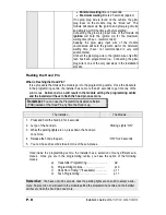
Note

: In diesel mode there is a 18-sec. crank timing 

delay (or approximately 25-sec. if the run time is set to 
30 min.): if the glow plug light is still on after the delay 
expires, the module will proceed to start the engine

(Also known as the “wait-to-start light”.) The purpose of 
the glow-plug circuit on diesel vehicles is to pre-heat the 
combustion chamber before the vehicle is started. 
When a remote starter is installed on a diesel vehicle, 
the glow plug section of the ignition circuit must be 
activated and allowed to operate before the vehicle is 
remote-started. For that purpose, the glow plug input 
wire of the module must be connected to the glow plug 
indicator light of the vehicle. The module will only accept 
positive glow plug input signals, if the signal is negative, 
use a relay to invert its polarity. A diode must be added 
between the negative glow plug trigger on the relay and 
the negative glow plug wire of the car. This is to prevent 
feedback effects on the glow plug indicator light on the 
instrument cluster: the light on the dash would come on 
because of the feedback, even though the circuit is off. 

When the user remote-starts the vehicle: 

The module will power up the ignition circuit and wait to 

engage the starter motor while the glow plug indicator 

light is still on. 

The module will engage the starter motor as soon as the 

glow plug light (+) goes out. 

Summary of Contents for AS-1414

Page 1: ...S T E M AS 1414 AS 1424 Installation Guide Table of Contents Introduction 2 Included in the Package 2 Before You Get Started 3 Harness Description 4 6 Pin Main Ignition Harness 4 5 Pin Secondary Harness 5 12 Pin Accessories Harness 5 Flashing the Hood Pin 8 The Programming Assistance Button A k a PAB 9 Before Programming a Transmitter 9 How to Program the Transmitter 9 How to Enter Programming Opt...

Page 2: ...emote transmitters AS 1424 Only 1 R 1 interconnect cable 1 R 1 receiver 1 Hood pin switch 1 6 Pin main ignition harness 1 5 Pin secondary harness 1 12 Pin accessories harness 1 Warning label user guide The plug in valet is not included INDUSTRY CANADA USER NOTICE Operation is subject to the following two conditions 1 this device may not cause interference and 2 this device must accept any interfer...

Page 3: ...idles properly Make sure that all safety equipment is installed the valet button if installed the Hood Switch and the warning label When wiring in parallel make sure to isolate each connection with a diode in order to avoid feedback and possible damage Examples Wiring a clutch bypass and a Transponder Module to the Ground Out when Running wire At the junction point where Ground Out when running sp...

Page 4: ...ble 12 volts source at the IGNITION switch the 12 Volt wire is too small to supply the necessary current In this case the fuse box or the B connection on the battery is recommended D YELLOW 30 A ignition output Connect to ignition wire of the vehicle The source wire should have 12 V with the ignition key in the IGNITION ON RUN and crank positions Warning some vehicles have more than one IGN wire a...

Page 5: ...pressed It is also used for programming and therefore it is essential that it is installed 5 YELLOW 12 V Parking Light output This wire provides a 12 V output 15 A max and must be connected to the parking light wire that tests 12 V when the parking lights are ON Note Ensure that the voltage does not vary when the dimmer control switch is turned up or down If this is the case it is not the right wi...

Page 6: ...king light output 9 PURPLE External Trigger input The external trigger wire can be used for remote starting the vehicle with an external device When the vehicle is running triggering this input will activate idle mode The external trigger wire can also be used to operate as a negative trigger with the trunk pin switch the key sense wire or the door pin switch Option 1 Connects to negative trunk pi...

Page 7: ...w plug light that is positive when the light is on Note In diesel mode there is a 18 sec crank timing delay or approximately 25 sec if the run time is set to 30 min if the glow plug light is still on after the delay expires the module will proceed to start the engine Also known as the wait to start light The purpose of the glow plug circuit on diesel vehicles is to pre heat the combustion chamber ...

Page 8: ...the programming centre the installer has no more than 20 seconds to get into one of the sub menus Failure to do so will result in the module exiting the programming centre and the installer will have to flash the hood pin once more Remember You can use the Programming Assistance Button PAB instead of the Hood Pin any time the Hood is up The Installer The Module 1 Press and hold the hood pin for 4 ...

Page 9: ...to the IGNITION ON RUN position and then to the OFF position 2 Press and hold the LOCK button until the vehicle gives 5 flashes The module has stored the transmitter in its memory 3 Close the hood to exit Table 1 How to Enter Programming Options Mode The system is equipped with two custom programming modes allowing the installer to custom fit the system according to the requirements of each vehicl...

Page 10: ...D FUNCTION 2 Secure Lock OPTION 1 Secure Lock DISABLED OPTION 2 Secure Lock ENABLE OPTION 3 Secure Lock DISABLED 1 2 SEC DISARM PULSE FUNCTION 3 Passive Active Arming of the Starter Kill OPTION 1 Starter Kill PASSIVE 1 minute timeout OPTION 2 Starter Kill ACTIVE OPTION 3 Starter Kill PASSIVE 3 minute timeout FUNCTION 4 Lock Pulse Duration OPTION 1 7 10 second LOCK UNLOCK pulses OPTION 2 4 second L...

Page 11: ...f once the tach signal is detected 4 Press and hold the brake pedal until the parking light output from the module flashes 5 times 5 Turn the ignition OFF At this point the tach setting has been programmed Table 4 Multi Speed Tach Programming The system is designed to read a wide range of tach signals produced by newer ignition systems No manual adjustments are necessary However you should go thro...

Page 12: ... Test the brake shutdown circuit with the vehicle running under the remote starter press and release the brake pedal The engine should shut down immediately If the engine continues to run check the brake switch connection 4 OEM alarm control Make sure the module is able to arm and disarm the OEM alarm if applicable 5 Door locks and trunk testing Make sure each of these options respond to the trans...

Page 13: ...causing the 30 A fuse to blow Always check your circuit with a proper measuring device Ignition controlled Door Locks OFF by default This feature will automatically lock all doors as soon as the key is turned to the IGNITION ON RUN position and the brake pedal is pressed When the ignition key is turned to the OFF position the doors will automatically unlock Secure Lock OFF by default This feature ...

Page 14: ...s option allows the user to engage the remote starter to take over the vehicle while it is already running This option will keep the vehicle running for the pre programmed run time or until it is shut down Resetting the Module without the plug in valet Resetting the module is not a required process Most of the time you can avoid resetting the module by fixing the issue directly at the root of the ...

Page 15: ...able radio frequency deflection in this case the signal from the remote control As a result the direction in which the vehicle is facing in relation to the remote control can affect the range Straight on standing in front of the vehicle generally gives you the greatest range the second best performance is from the back Using the remote control from either side of the vehicle will usually give the ...

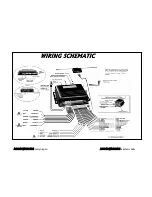
Page 16: ...AS 1414 AS 1424 Wiring Diagram AS 1414 AS 1424 Installation Guide ...

Reviews: