background image

P. 20

 Installation 

Guide


Clutch Bypass 

In order to remote start a manual transmission vehicle, the clutch switch must be bypassed. Clutch 
safety switch circuits can take many forms. Listed below are the most common ones. Some 
vehicles may also have a separate or combined switch on the clutch pedal for cruise control. 
Usually a cruise control switch reacts the moment you touch the pedal, whereas a clutch switch 
reacts only when the pedal is near the floor. Once the circuit type has been determined, you must 
recreate what happens electrically at the switch, with the remote start module, to bypass the clutch 
during remote starts. Relays are often used to accomplish this. Always use the Ground Out When 
Running (G.O.) as the negative trigger on your clutch bypass relays, as it is only active during 
remote starts. NEVER permanently bypass a clutch switch. Do not attempt this if you are unfamiliar 
with the use of relays and diode isolation.  


Before any wiring attempts, test and record the way each wire tests in the following 
positions:  
Without the pedal pressed


test the wire with the Ignition 

OFF


test the wire with the Ignition 

ON


test the wire with the Key in the start position 

With the pedal pressed: 


test the wire with the Ignition 

OFF


test the wire with the Ignition 

ON


test the wire with the Key in the start position 

With this information for every wire at the switch, determining what type of clutch switching system 
you have will be easy. 


Direct Feed: 

The simplest type of system to test and bypass is the “Direct Feed” system. This circuit simply 
interrupts the +12v signal starter wire from the ignition switch to the starter solenoid. There are 2 
wires in this circuit, the “key side” wire which goes from the clutch pedal to the Ignition switch, and 
the “solenoid side” which goes from the clutch switch to the starter motor. When the key is turned 
to the start position without pressing the pedal, you will test 12v only on one of the wires at the 
clutch switch; this is the key side. When the pedal is pressed down and the key is in the crank 
position, the other wire will also read 12 volts; this is the solenoid side wire. Connect the starter 
output from the remote starter to solenoid side wire.  


Note: 

In the next two systems a Relay in the vehicle interrupts the start wire between the Ignition 

switch and the starter motor. With the key in the start position and the clutch pedal pressed, the 
relay energizes and allows the start signal to reach the starter motor. In these systems a wires from 
the clutch triggers the relay when the pedal is pressed. There will be another wire at the clutch 
switch that supplies the signal to the trigger wire (either positive or negative, depending on the 
system). 


Negative: 

 In a Negative system, when the clutch is pressed, a negative signal is sent to the relay. The relay 
energizes when the Key is turned to the start position. The 12volts from the start wire is allowed to 
pass through the relay and to the starter motor. One of the wires at the clutch will test as negative; 
this is the supply wire. The relay's negative trigger wire will only show negative when the pedal is 
pressed (some vehicles also require the Ignition system to be powered). If there is nothing else 
connected to the Ground Out When Running (G.O.) wire from the remote start module, the G.O. 
wire should be strong enough to trigger the vehicle's clutch relay. If there are other devices or 
modules connected to the G.O. Wire, a relay (and diodes) may have to be added to strengthen the 
negative current going to the clutch bypass.  

Summary of Contents for AS-3472TW-FM

Page 1: ...n guide carefully before beginning any work Warning Before installing the unit if installing on a vehicle with a manual transmission test that the OEM Door Switch contacts of the vehicle work well and...

Page 2: ...rter Kill Arming Mode 22 Lock Pulse Duration 22 Flashing LED 22 Safe Start 23 Engine Run Time 23 Idle Mode 23 Turbo Mode 24 Cold Weather Mode 24 Valet Mode 25 Home Valet Mode 26 Panic Mode 27 The AUX...

Page 3: ...rew drivers Socket set wrench set drill with drill bits plastic fish tool for fishing wires through the firewall Installation Points to Remember On vehicles with a manual transmission always ensure th...

Page 4: ...there are numerous other scenarios where diode isolation is required Always make sure that any external relays or modules added to the Remote Starter module are properly fused and diode isolated When...

Page 5: ...e engine bay Under the driver s side of the dash there is usually enough room for the module to fit Once the location has been decided proceed to the next step Mount the antenna and run the cable to t...

Page 6: ...e made This extra bit of wire is wrapped around the exposed OEM wire to secure in place while you are soldering When all of the wires have been connected solder the connections When the solder has coo...

Page 7: ...nected to 30 87A Normally Closed N C When the coil is at rest 87A is connected to 30 30 Common When the relay is at rest 30 is connected to 87A When the coil is energized it is then moved and makes co...

Page 8: ...for powering multiple wires from one source SAFELY Powering multiple wires from one source safely Example Powering a second Ignition Problem You need to power Multiple Ignition wires to remote start...

Page 9: ...t The side that is still connected to the switch becomes the Switch Side The side that is still connected to the Parking lights becomes Parking Lights Side 87A Connects to the Switch Side of the cut O...

Page 10: ...lly The Starter Kill output wire on the remote start module is activated when the LOCK button is pressed on the remote control When a theft attempt happens and the thief powers the Ignition circuit to...

Page 11: ...y current In this case the fuse box or the B connection on the battery is recommended If wires need to be extended you must protect them with additional fuses connected at the entry source 4 PINK 30 A...

Page 12: ...refore it is essential that it is installed 5 WHITE 12 V Parking Light output This wire provides a 12 V output 15 A max and must be connected to the Parking Light wire that tests 12 V when the Parking...

Page 13: ...seconds after the Trunk is closed An ARM pulse will be sent 4 seconds after the TRUNK button is pressed if the Trunk pin state is unchanged The Trunk was unopened Disarm is sent only if the system was...

Page 14: ...connecting the glow plug input to the vehicle 3 pin Harness Wire Description 1 VIOLET BLACK AUX 2 Output 500 mA negative output Can be programmed for one of the following four options 1 Constant while...

Page 15: ...s the hood pin once more and release immediately The parking lights will turn ON and stay ON for 20 seconds Within 5 seconds press the programming button on the antenna twice for 1 second each time Th...

Page 16: ...emote start the system will lock the transmission settings to manual mode To install this unit in a vehicle with an automatic transmission 1 Cut the loop on the pc board Yellow wire 2 Make sure the Bl...

Page 17: ...PTION 3 7 10 sec lock pulse and two 1 4 sec unlock pulses OPTION 4 1 10 sec lock unlock pulses FEATURE 5 LED flashing OPTION 1 ENABLED without starter kill will flash only when ignition is OFF OPTION...

Page 18: ...DEFAULT SETTING FEATURE 1 Alarm Control OPTION 1 ENABLED HORN must be enabled OPTION 2 DISABLED FEATURE 2 Ready Mode Option OPTION 1 Enabled by handbrake OPTION 2 Enabled by remote FEATURE 3 Bypass O...

Page 19: ...ters of this series are equipped with an on board high current programmable 5th relay that can be used to power a second ignition accessory or crank wire The unit uses 3 sets of pins each set correspo...

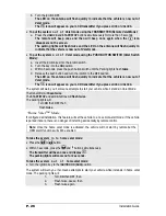
Page 20: ...is circuit the key side wire which goes from the clutch pedal to the Ignition switch and the solenoid side which goes from the clutch switch to the starter motor When the key is turned to the start po...

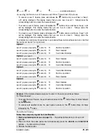
Page 21: ...ire this disengages the relay To verify that you have a N C system disconnect the clutch switch the vehicle should start without the clutch pedal being pressed When you test the trigger wire with your...

Page 22: ...n preceding the activation of the Starter Kill Once the activation countdown expires the LED will send a series of quick double flashes to indicate that the Starter Kill is now armed To disarm the Sta...

Page 23: ...rammed to run the engine for 3 15 or 25 minutes 15 minutes by default On a diesel engine the Remote Car Starter can be programmed to run the engine for 8 20 or 30 minutes 20 minutes by default Idle Mo...

Page 24: ...ady Mode Option in this Guide to activate Turbo Mode At the last step press either 1 LOCK to lock the doors and have the engine shut down after 60 seconds The parking lights will flash 3 times and rem...

Page 25: ...RUN and OFF positions The parking lights will flash three times b Turn the ignition OFF The LED on the antenna will come ON solid to indicate that the vehicle has successfully entered Valet mode The i...

Page 26: ...e that the vehicle is now out of Valet mode The icon will appear on your LCD transmitter if you press LOCK or UNLOCK The system will warn you if someone attempts to start your vehicle while it stands...

Page 27: ...priority door access but also as trunk release Horn Confirmation AUX 1 can be programmed to trigger the horn every time the LOCK button is pressed or when the LOCK button is pressed twice within 3 sec...

Page 28: ...Ready Mode is enabled by remote If Ready Mode is enabled by handbrake 1 Ensure that all the doors hood and trunk are closed Make sure that the gear selector is in the neutral position 2 With the engi...

Page 29: ...ress TRUNK LCD Transmitter Operation and Confirmations Second Car Control Basic Operations Function Button pressed Icon Sound Lock 1 beep Unlock 2 beeps Start Melody Stop None Melody Trunk 1 Beep Star...

Page 30: ...the display did not return to its basic state simply press the button this will refresh the display If the engine was stopped the icon will disappear and the time will be displayed Pressing the butto...

Page 31: ...vel 3 requires pressing the button 3X Customized features Option 2 on by default Level 1 requires pressing the button 1X Basic features Level 2 requires pressing the button 2X Multi car operation Leve...

Page 32: ...the result of misunderstandings about how a product works or performs Take the time to properly explain all functions and features to the customers before they leave the premises Doing this will save...

Page 33: ...ge of the transmitter Some of these are The condition of the battery in the transmitter The operating environment for example downtown radio frequency noise airports cellular phone towers Metal any ty...

Page 34: ...em Board set from automatic to manual power ON Power ON to OFF manual transmission 5 Fast Tach signal programmed New transmitter programmed 6 A remote start was attempted while a tach before crank sig...

Page 35: ...but the car will not start Are you on the correct ignition wire Does the car have more than 1 ignition 4 The car cranks briefly then quits Have you bypassed the passive security PASSLOCK PASSKEY III P...

Page 36: ...cks cars and mini vans 18 The car runs for about 5 seconds shuts down and restarts it does this 3 times Check voltage on tach wire Try an alternate tach source 19 The car starts by remote but the rang...

Page 37: ...mote door locks and I have already installed a relay Door locks are reverse polarity and not positive trigger 26 I blow fuses every time I try the remote trunk release and I have already installed a r...

Reviews: