
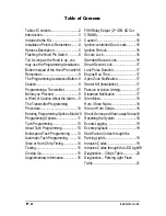

P. 4
Installation Guide
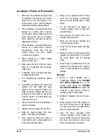
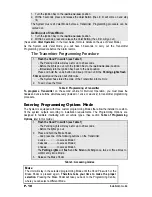
Installation Points to Remember
•
Make sure that vehicles equipped with
an automatic Transmission do not start
while in any of the Drive Gears. If the
vehicle starts in gear, install a Manual-
transmission Remote Starter instead.
•
When installing a manual-transmission
product on a vehicle with a manual
Transmission, always make sure that all
Doors will get the Unit out of Ready
Mode. Switch the wire used so that it is
triggered by all Doors.
•
When installing a manual-transmission
product on a vehicle with a manual
Transmission, make sure that the
Parking Brake and Door Switch
contacts work properly.
•
When working on a vehicle, always
leave a window open.
•
Never leave the keys in the car. Leave
them on a workbench with a window
rolled down.
•
If possible, remove courtesy light fuse
to prevent battery drain.
•
The Programming Assistance Button
(PAB)
•
The PAB is mounted on the side of the
System unit and fulfils the same
function as the Hood-Pin Switch. The
PAB will spare installers the effort of
getting out of the vehicle to access the
Hood-Pin Switch. The PAB works only
when the Hood is up.
•
Inspect vehicle for any body damage or
electrical problems
•
Always solder and tape all connections.
•
Keep the Antenna away from other
types of antennas (GPS/OnStar).
•
Never install the control unit where it
could interfere with normal operation or
obstruct service technicians.
•
Always use a grommet when running
wires into the Engine compartment.
Never run wires through bare or sharp
metal.
•
Do not disconnect the battery on
vehicles equipped with air bags and
anti-theft radios.
•
Never ground the control unit to the
vehicle’s steering column.
•
Make sure that all the switches and
controls operate properly.
•
Verify that the vehicle starts and idles
properly.
•
Make sure that all safety equipment is
installed: the Valet Button (if provided),
the Hood Switch and the Warning
Label.
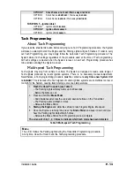
•
When wiring in parallel, make sure you
isolate each connection with a diode in
order to avoid feedback and possible
damage.
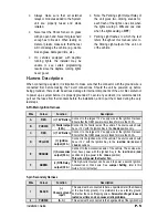
Examples:
•
Wiring a Clutch Bypass and a
Transponder Module to the
GROUND
OUT WHEN RUNNING
wire: At the
junction point, where the
GROUND
OUT WHEN RUNNING
wire “splits” and
connects to each device, a diode is
inserted on each of these lines.
•
Multiple or separate Door pin Connec -
tions:
•
When joining all Door Pins together to
the Door Pin input wire of the System
unit, each wire must be isolated with a
diode to prevent feedback.
•
Note: The above examples reflect
common situations where diodes are
use to isolate connections. Please note
that there are numerous other cases
where diode isolation is required.


