Notice
The manufacturer will accept no responsibility for any electrical damage resulting from improper installation of the product, be
that either damage to the vehicle itself or to the Unit. This Unit must be installed by a certified technician using all safety devices
supplied. Only registered technicians will be eligible to use the Autostart technical support telephone service.
Please review the Installation Guide carefully before beginning any work.
Warning
This unit is designed for vehicles with an
automatic
Transmission only. Before installing the Unit, test that the vehicle
does not start when the gear select lever is in the “Drive” position. If it starts in gear, install a manual-transmission car starter
A U T O M A T I C
T R A N S M I S S I O N M U L T I - C H A N N E L R E M O T E S T A R T E R S Y S T E M
PS-2925
Installation Guide
Table of Contents
Table of Contents................................................................1
Introduction .........................................................................2
Included in the Kit ...........................................................2
Before You Get
Started
…...............................................2
Installation Points to Remember.....................................3
PS-2925 Features List....................................................3
Plug-ins...........................................................................3
Harness Description............................................................4
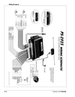
Wiring Diagram ...................................................................6
Transmitter Functions .........................................................7
Programming a Transmitter ................................................7
Multi-Speed Tach Learning.................................................7
The Programming Assistance Button .................................8
Valet Operation ...................................................................8
Programming Options .........................................................8
Programmable Features .....................................................9
Ignition-controlled Door Locks ........................................9
Secure Lock....................................................................9
Passive or Active Arming ............................................... 9
Lock Pulse Duration..................................................... 10
Engine Run Time ......................................................... 10
Idle Mode ..................................................................... 10
Other Features of the Module .......................................... 11
Ground Out When Running ......................................... 11
Starter Kill Circuit (Installation)..................................... 11
2
nd
Ignition / Accessories / Crank Relay Output........... 11
External Trigger ........................................................... 11
The Trunk Output......................................................... 12
Cold Weather Mode ..................................................... 12
Multi-car Operation ...................................................... 12
Events Logging and Playback...................................... 13
Resetting the Module ....................................................... 13
Diagnostics - Parking Lights Flash Rate .......................... 13
Testing.............................................................................. 14
Troubleshooting Poor Transmitting Range....................... 13
Closing Up........................................................................ 14
instead.
H.1.20.S.2.00
Rev.1.06– August 5, 2002
β
.2.05 – Gf Fb Gp CA
Manufactured in Canada by Autostart


