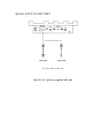
Fig. 1 Installation of amplifier
Power Supply Connections
The +12VDC and ground wires should be heavy gauge standard copper wire with heavy insulation. The
wire gauge should be 4AWG for the 300.S, 400.S, 500.S or larger. In addition it has a 12V remote control
wire and it should be 14AWG-18AWG. It is preferable to have longer speaker wires and shorter power
supply wires to minimize power losses.
+12V Power
This wire is usually connected directly to the positive battery terminal. Ensure that the + power supply wire
is fused via an assigned fuse in line with the + power supply wire. This connection must be completed by
using spade lug with insulating sleeve.
Ground
This connection must be completed by using spade lug with insulating sleeve. This wire is the electrical
ground and must be fastened securely to the vehicle chassis. The best method is to use a shelf threading
sheet metal screw since the threads cut into bare metal. Ensure that all paint coating or other insulation is
removed from around the hole are and using self tapping screw, securely affix the bare wire ends to the
vehicle chassis. Use as short a piece of cable as possible —use the same gauge as for the +12V.
Remote
Many radios or other music sources have an output terminal for connection of the remote turn -on of the
power amplifier. If a radio doesn’t have a remote turn-on feature, then you can use the antenna relay wire
which activates the antenna motor. But you must take notice if the power antenna retracts when the tape
player is operating. In this case, you can’t use the antenna relay wire to operate the remote turn-on.


