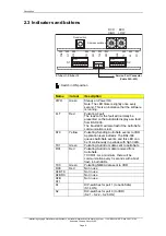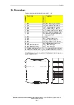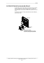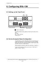
Description
2.3 Indicators and buttons
0
12
34
5
678
9
0
12
34
5
678
9
Reset switch
Address switches
BCD
HIGH
BCD
LOW
PWR
FL
T.
ST0
TX1
RX1
TX0
RX0
AFB:
TX
RX
ST1
1 2 3 4 5 6 7
ON
S1
S2
1 2 3 4 5 6 7
ON
Service-Port Connector
(Cable XJA-029)
S1=Port 1, S2=Port 0
=
Switch in ON position
Interfacing Voyage Data Recorder Systems, AutroSafe Interactive Fire-Alarm System, 116-P-BSL336/EE, RevA 2007-01-25,
Autronica Fire and Security AS
Page 6
Name
Colour
Description
PWR
Green
Steady on: Power OK
Note: The LED flickers slightly once every
second. This is an indication that the software
is running.
FLT Red Pulsating:
Fault
The reason for the fault will normally be
presented on the AutroSafe display as a fault
from BSD-336.
The Fault LED will also flash if the AutroSafe
communication is lost.
ST0 Yellow
Pulsating:
Sending
AutroSafe events to VDR.
Application level indicator: The BSL-336
queues AutroSafe events, and this LED can
be lit continuously in periods with high traffic.
TX1 Green Pulsating:
AutroCom data sent to AutroSafe
RX1
Red
Pulsating: AutroCom data received from
AutroSafe.
TX1/RX1: As a minimum, there will be
communication every 3 seconds with a brief
flash in both LEDs.
TX0
Green
Pulsating: NMEA data sent to VDR
RX0
Red
Not in use
AFB TX
Not in use
AFB RX
Not in use
AFB
ST1
Not in use
S1
DIP-switches for port 1 (to AutroSafe)
(S1.4 ON)
S2
DIP-switches for port 0 (to VDR)
(S2.1 – S2.2 – S2.5 ON)


