BA-45 – Control Panel for Extinguishing Systems
Autronica Fire and Security AS
Fire and Security, Trondheim, Norway.
Phone: + 47 73 58 25 00, fax: + 47 73 58 25 01
Oil & Gas, Stavanger, Norway.
Phone: + 47 51 84 09 00, fax: + 47 51 84 09 99
Visit Autronica Fire and Security’s Web site: www.autronicafire.com
1st. Alarm
Extinguishant released
Autom. release
inhibited
Ext. output
inhibited
Fault release output
Low tank pressure
Fault control inputs
Fault man./aut./
pressure circuit
ZONE 2
1st. Alarm
Extinguishant released
Autom. release
inhibited
Ext. output
inhibited
Fault release output
Low tank pressure
Fault control inputs
Fault man./aut./
pressure circuit
ZONE 1
Fault power supply
Control Panel for
Extinguishing Systems
COMMON
Reset
Fault alarm output
Power
Silence sounders
Lamptest
BA-45
1st. Alarm
Extinguishant released
Autom. release
inhibited
Ext. output
inhibited
Fault release output
Low tank pressure
Fault control inputs
Fault man./aut./
pressure circuit
ZONE 2
1st. Alarm
Extinguishant released
Autom. release
inhibited
Ext. output
inhibited
Fault release output
Low tank pressure
Fault control inputs
Fault man./aut./
pressure circuit
ZONE 1
Fault power supply
Control Panel for
Extinguishing Systems
COMMON
Reset
Fault alarm output
Power
Silence sounders
Lamptest
BA-45
LED indicators (continued)
•
Yellow indicator for power supply failure. Activated in case of
power failure on one of the power circuits and communication
failure between the front panel and the integrated Extinguish-
ing Release Module BA-40.
•
Green indicator for operating power. Indicates that one of the
two power inputs is supplied with power.
•
Yellow indicator for failure on sounder alarm output.
Operating Buttons
•
Silence Alarm, Reset and Lamptest.
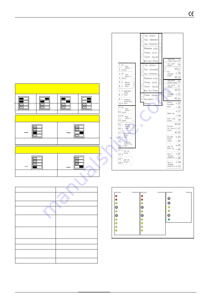
DIP-switch S1
DIP-switch S1 is mounted on the integrated Extinguishing Re-
lease Module BA-40 on the left uppermost side. Note that the
switch is shown as if the unit is hold in upright position.
Delay period for release of extinguisher after activation of
one of the control inputs.
Settings on S1.1 and S1.2.
(Factory settings: 60 seconds)
OFF
ON
1
2
3
4
OFF
ON
1
2
3
4
OFF
ON
1
2
3
4
OFF
ON
1
2
3
4
0 seconds
30 seconds
60 seconds
180 seconds
Status common fault signal (output 39) / Settings on S1.3.
(Factory settings: Normal)
OFF
ON
1
2
3
4
OFF
ON
1
2
3
4
Normal
Gives 0-volt control at failure.
Reverted
Breaks 0-volt control at failure.
Status for monitoring signal input/ Settings S1.4
(Factory settings: OFF)
OFF
ON
1
2
3
4
OFF
ON
1
2
3
4
Break and short circuit
monitored.
Break monitored only.
Technical Specifications
Connections / Indicators on the integrated
Extinguishing Release Module BA-40
Front panel, Indicators and Switches
Dimensions (AutroSafe)
HxWxD = 350x350x194 mm
Dimensions (conventional
systems)
HxWxD = 350x350x84 mm
Weight
5,5 kg
Material
Steel cabinet, ABS/PC-cast
front
Power consumption (normal)
1 zone
2 zones
70 mA
80 mA
Power consumption (alarm)
1 zone
2 zones
1,5A
3A
Ambient temperature
-5 til + 40
°
C
Power supply
Duplicated 24VDC/1,5A
Release effect
(at 24V DC)
25W continuous.
70W<1 seconds
Protection class
IE529/IP30
S1.3.
S1.3
S1.4
S1.4
Indicators
Connectors
S1.1 Release Delay
S1.2 Release Delay
S1.3 Fault inv.
S1.4 Monitoring
Connec-


