VERSION 1.9
J120 (38198-X)
Devices
IMU (MPU-9250)
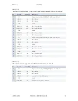
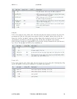
A 9 axis sensor is connected to the SPI0 bus of the TX1. Pin 8 (VddIO) of the IMU is connected to 1.8V. Please
set the INT output of the IMU by software to „totem pole“ mode as there is no pull-up on the INT output.
This IMU is optional. Only some J120 models are equipped with this function.
SPI busses with the Jetson TX1
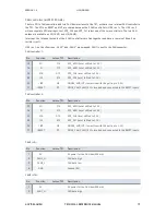
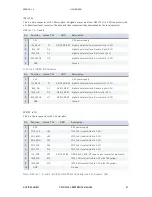
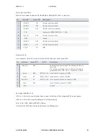
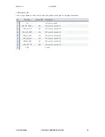
The Jetson TX1 features 3 SPI busses: SPI0 to SPI2. The table below lists how these SPI devices are mounted.
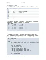
Please note how the 5 physical SPI devices relate to the 5 spidevs.
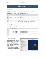
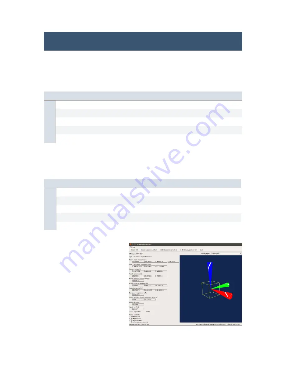
Test of the IMU with the
RTIMULibDemo
This demo may be downloaded from Github.
Please install qtcreator first. Next please
make sure that the spidev3.0 device in /dev
is loaded. Edit the RTIMUlibDemo.ini file
with the SPI settings for the IMU (bus 3,
select 0). Start the demo as root so it gets
access to the SPI bus.
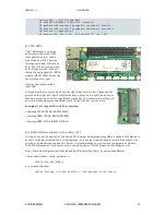
The IMU chip is located on the bottom side
next to the JTAG connector. The IMU is
optional on the J120. Please make sure that
your J120 has the IMU installed.
Pin
Function
Jetson TX1
Description
9
AD0/SDO
E4
SPI0_MISO (1.8V)
24
SDA/SDI
F4
SPI0_MOSI (1.8V)
23
SCL/SCLK
E3
SPI0_CLK (1.8V)
22
/CS
F3
SPI0_CS0 (1.8V)
12
INT
G14
INT is inverted and connected to GPIO9_MOTION_INT (1.8V)
Bus
CS
Tegra X1 SPI device
Use
SPI0
0
SPI4
spidev3.0
IMU MPU-9250
SPI1
0
SPI1
spidev0.0
CAN controller 1 (MCP2515)
SPI1
1
SPI1
spidev0.1
CAN Controller 2 (MCP2515)
SPI2
0
SPI2
spidev1.0
I2C/SPI connector J13
SPI2
1
SPI2
spidev1.1
I2C/SPI connector J14
AUVIDEA GMBH
TECHNICAL REFERENCE MANUAL
10


