JNX30D TECHNICAL REFERENCE MANUAL
VERSION: 1.4
Page 10 of 28
FEB 2022
SECTION 5
Pinout description
Please note that the software GPIO number differs from the socket pin number. This software GPIO
number must be computed with a special formula and differs between the various compute
modules. Please see appendix B for details.
5.1
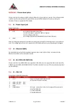
J1 - Power input jack
Barrel 5.5/2.5mm
Pin
Description
Note
1
12V
12V nominal (absolute max. 19V)
recommend power supply 12V 36W (or higher)
reverse voltage protection
over voltage protection (SMA6J18A/CA) with max 20V peak
2
GND
Reverse voltage protection also functions as back power protection if PoE injection is used with J32
pin 2. If a voltage higher than 19V is applied, the TRS diode will heat up and possibly get damaged.
5.2
J3 - Ethernet (GbE)
Standard RJ45 pinout with PoE capable magnetics class 3 and 4 (PD or PSE). Connected to the
Ethernet controller on the compute module.
5.3
J4 - M.2 PCIEx4 NVME SSDs
Please note that only NVME SSDs are supported. SATA SSDs are not supported. We recommend the
128GB Transcend SSDs (TS128GMTE110S). This SSD is standard in some of the Auvidea development
system offerings.
5.4
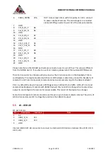
J5 - CSI-2 CD
22 pin 0.5mm pitch FPC connector
Pin
Description
Socket pin
Note
1
3.3V
Power: connected with bead to 3.3V
(5V optional if bead is moved)
2
GEN1_I2C_SDA 187
3
GEN1_I2C_SCL
185
4
GND
5
CAM2-MCLK
IN: Input - connect to 1.8V or 3.3V output of the camera to
drive the CAM LED.
1: enable CAM LED
0: disable CAM LED


