background image

22

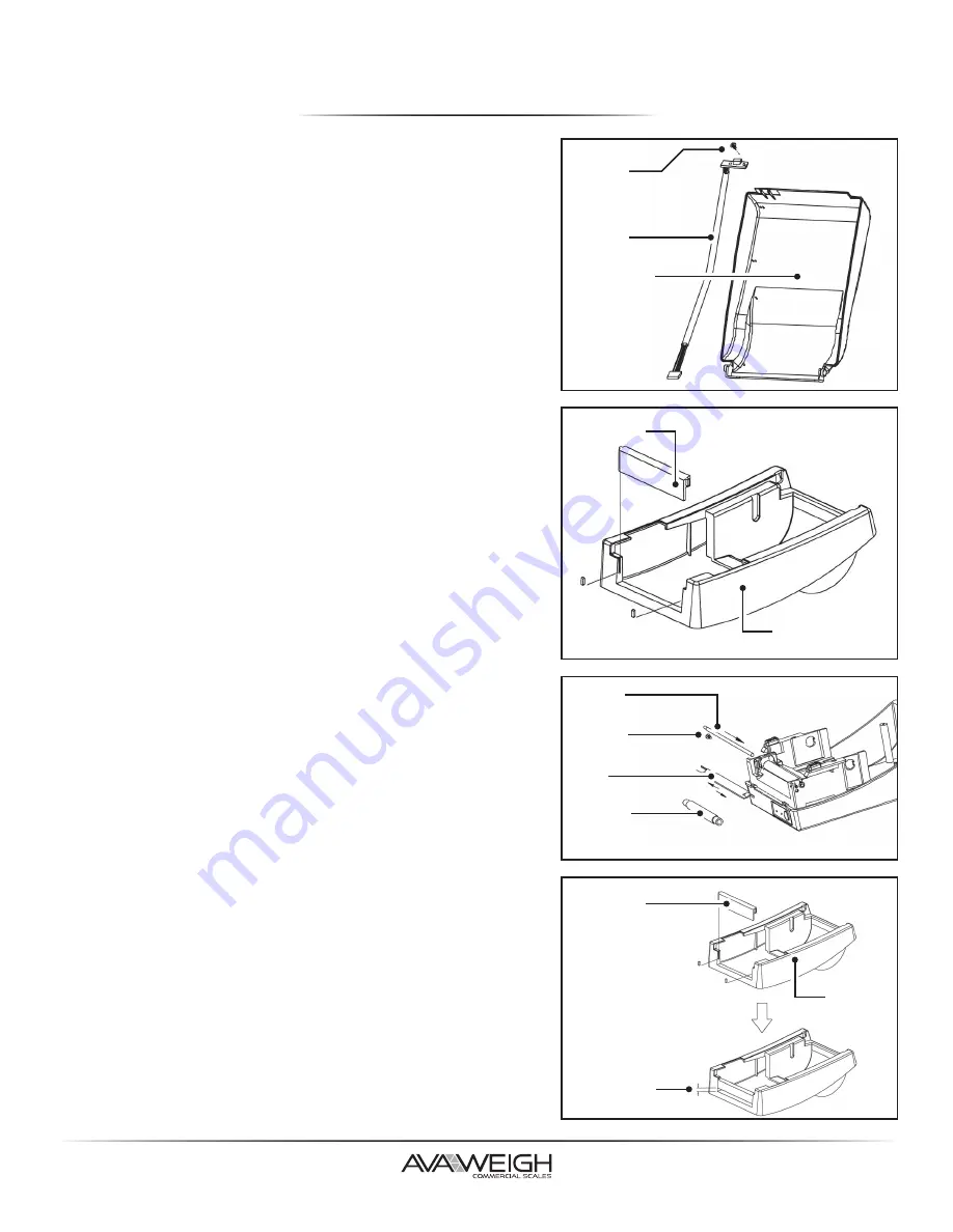
PEELER INSTALLATION

1.  Turn off the power switch.
2.  Unwrap the PC bag of the peeler to take out the 

screw, the shaft, the plastic roller, the peeler bar, 

the direction label, and the peeler sensor cable.

3.  Take off the top cover of the printer.
4.  Fix the sensor board on the top left cover and 

secure the screw. 

Keep the cable to the left.

5.  Rout the peeler sensor cable through the guides 

along the left side of the top cover.

6.  Release the (2) screws at the bottom of the base 

housing.

7.  Remove the middle cover.
8.  Take off the H Cover.
9.  Tape the direction label on top of the H Cover with 

the arrow sign facing away from you.

10. Release the screw on the left bracket of the chassis.
11. Unlatch the Print Head Module. Hook the white 

roller on the brackets of the chassis, ensuring the 

long thin end is to the left side.

12. Guide the shaft and go through the respective holes 

on the left bracket, the white roller, and the right 

bracket in order.

13. Secure the attached screw at right bracket of the 

chassis to fix the shaft.

14. Hook the peeler bar on the brackets of the chassis, 

positioning it above the white roller. Ensure that the 

peeler bar is paralleled with the black platen roller 

and its long thin end is to the left.

15. Plug the sensor board's connector into the PCB's 

header connector (J2).

16. Secure the screw on the left bracket of the chassis.
17. Guide the sensor cable connector through the hole 

on the upper left corner of the middle cover.

18. Click the top cover back to the middle cover.
19. Insert the sensor connector into its receptacle on 

the main logic board of the base housing.

20. Click the middle cover back to the base housing. 

First click in the front part, then the rear.

21. Secure the (2) screws at the bottom of the base 

housing.

Screw

Sensor 

Cable
Top Cover

H Cover

Shaft

Screw
Dispenser 

Bar

White 

Plastic Roller

Middle Cover

H Cover

4mm Gap

Middle 

Cover

Summary of Contents for 334PRINTER

Page 1: ...09 2020 1 334PRINTER Thermal Label Printer for Price Computing Scales USER MANUAL...

Page 2: ...o Factory Defaults 10 Printer Controls Indicators 10 Troubleshooting LED Buzzer Indicators 11 Miscellaneous 11 Recovery 12 Communications 12 Interfaces and Requirements 12 Communicating with the Print...

Page 3: ...t has been tested and found to comply with the limits for a Class A digital device pursuant to Part 15 of the FCC Rules These limits are designed to provide reasonable protection against harmful inter...

Page 4: ...the printer to see if all parts are in order Check whether you have received the following accessories together with the printer If there are any items missing please contact your local dealer Printe...

Page 5: ...p Cover Paper Outlet Power Switch Cover Lock Feed Button Power Indicator Ready Indicator RS 232 Serial USB Power Jack Cash Drawer Port Media Hanger Release Levers Thermal Print Head Media Guides OVERV...

Page 6: ...hould read 232 oUt Once you have confirmed you are on the label length screen please select the number associated with the length and type of label you will be using Press 1 40mm length date will prin...

Page 7: ...0 Data Type Unit price screen should read USb dFt confirming you are on the data type screen Press 1 8N1 8 bits data Press Enter to confirm your selection 11 Department Code Unit price screen will rea...

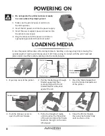
Page 8: ...rinter 4 Push the Release Levers to open the Printer Module 5 Pull a short length of media until it reaches the Platen Roll of the printer Adjust the Media Guide on the right so the roll is left align...

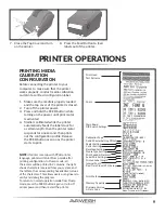
Page 9: ...the configuration profile Release the FEED button as soon as the printer starts to print NOTE If printer is set up with PPLB printer language printer will enter Dump mode after printing configuration...

Page 10: ...peration I Position OFF Turns power off O Position NOTE Turn power OFF before connecting or disconnecting cables POWER INDICATOR OFF Printer power OFF GREEN Printer power ON BLINKING Media Out or Medi...

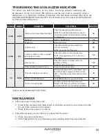
Page 11: ...ION BUZZER BLINK BLINK Media sensor cannot index label gaps Check the label path and label sensor NOTE If a continuous label roll is in use set continuous media printing in driver settings or commands...

Page 12: ...You must insert the power supply s barrel connector into the power jack on the back of the printer before connecting communication cables This printer complies with FCC Rules and Regulations Part 15 f...

Page 13: ...ting your Drivers by Seagull Even though the Add Printer Wizard is from Microsoft it too easily performs a number of tasks incorrectly when updating The bundled printer driver can be applied to applic...

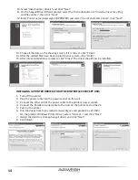
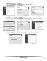
Page 14: ...o keep Seagull driver and click Next 8 Click Finish 13 Check all the data on the showing screen if it is correct click Finish 14 After the related files have been copied to your system click Finish 15...

Page 15: ...ct the port of the printer and click Next 13 Enter printer name Avaweigh 334PRINTER and select Do not share this printer click Next 14 Check all the data on the showing screen if it is correct click F...

Page 16: ...any possible damage please use the Print Head Cleaning Pen or soft cloth cotton buds with Ethanol or Industry Alcohol to clean Print Head surface It s strongly recommended to wear gloves during cleani...

Page 17: ...PC A UPC E UPC interleaved 2 of 5 Code 39 with check sum digit Code 93 EAN 13 EAN 8 Standard 2 5 digit add on Codabar Postnet Code 128 subset A B C Code 128 UCC shipping container code Code 128 auto U...

Page 18: ...ECC 200 only QR code Composite codes Code 39 Std Extended UPC A UPC E UPC interleaved 2 of 5 Code 39 with check sum digit Code 93 EAN 13 EAN 8 Standard 2 5 digit add on Codabar Postnet Code128 subset...

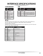
Page 19: ...3 Input RX 4 Shorted to Pin 1 6 5 Ground 6 Shorted to Pin 1 4 7 Input CTS 8 Output RTS 9 Output 5V CASH DRAWER USB RS232 The RS232 connector on the printer side is a female DB 9 and pin to pin standar...

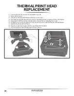
Page 20: ...nt Head firmly into the mounting bracket to release it from the Module 5 Disassemble the Thermal Print Head and the metal plate by removing the screws 6 Unplug the 2 print head cables from the connect...

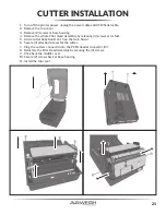
Page 21: ...le Print Head Assembly by releasing 4 screws at its feet 5 Add a cutter baby board on J5 on the main board 6 Secure 3 attached screws for the cutter 7 Plug the cutter s connector into the PCB s header...

Page 22: ...d go through the respective holes on the left bracket the white roller and the right bracket in order 13 Secure the attached screw at right bracket of the chassis to fix the shaft 14 Hook the peeler b...

Reviews: