background image


  1.2 - SHIPPING AND TRANSPORTING  


The pump will always be moved in a vertical (and never in a horizontal) position. No matter what the means 
of transport employed, delivery of the pump, even when free to purchasers or the addressee’s domicile, is 
always at the purchaser’s risk. Claim for any missing materials must be made within 10 days of arrival, while 
claims for defective  materials will be  considered up to the 30

th

  day  following receipt. Return of pump or 

other  materials  to  us  or  the  authorized  distributor  must  be  agreed  beforehand  with  the  responsible 
personnel. Material should be  disassembled and packed with care. All parts  in contact  with the  chemical 
should be purged and rinsed for everyone’s safety. In the case of non-compliance with this guideline, we 
reserve  not  to  support  the  materials  and  to  return  it  at  your  expense  and  any  damage  created  by  the 
chemical on the material will undergo a repair quote. 

  1.3 - PROPER USE OF THE PUMP 


The pump should be used only for the purpose for which it has been expressly designed namely the dosing 
of  liquids.  Install  the  pump  in  a  dry  place  and  well  away  from  sources  of  heat,  and  in  any  case,  at 
environmental  temperature  not  exceeding  40°C.  The  operating  minimum  temperature  depends  of  the 
liquid to be pumped, bearing in mind that it must always remain in a liquid state. Any different use is to be 
considered dangerous. The pump should not therefore be used for applications that were not allowed for 
in its design. In case of doubt please contact our offices for further information about the characteristics of 
the  pump  and  it  proper  use.  The  manufactures  can  not  be  held  responsible  for  damage  deriving  for 
improper, erroneous or unreasonable use of the pump.  
 

  1.4 - RISKS 


• After unpacking the pump, make sure that it is completely sound. In case of doubt, do not use the pump 
and contact qualified personnel. The packing materials (plastic bags, polystyrene, etc.) should be kept out 
of the reach of children: they constitute potential sources of danger. 
• Before you connect the pump make sure that the voltage ratings correspond to your particular voltage 
supply. You will find this value on the rating plates attached to the pump. 
•  The  electrical  installation  to  which  the  pump  is  connected  must  comply  with  the  standards  and  good 
practice rule in force in the country under consideration. 
Use of electrical equipment always implies observance of some basic rules. In particular:  

Do not touch with wet or damp hands or feet. 

Do not operate the pump with bare feet (typical place: swimming pool ) 

Do not leave the equipment exposed to the atmospheric agents 

Do not allow the pump to be used by children or unskilled individuals without supervision 

• The pump has to be supplied through an isolating transformer or supplied through a RDC ( max operating 
current = 30mA ). 
•  In  case  of  breakdown  or  improper  functioning  of  the  pump,  switch  off,  but  do  not  touch.  Contact  our 
technical assistance for any necessary repairs and insist on the use of original spares. Failure to respect this 
condition could render the pump unsafe to use. 
• In case of damage of power supply cord please ask the repair to our technical assistance or qualified and 
authorized personnel. 
• When you decide to make no further of an installed pump, make sure to disconnect it from the power 
supply. 

Summary of Contents for POOLeasy pH

Page 1: ...INSTRUCTIONS AND USER MANUAL POOLeasy pH POOLeasy Rx Power at the service of water...

Page 2: ...LLATION AND RECOMMENDATIONS 6 4 1 Recommendations 6 4 2 Principle of hydraulic and electrical installation 7 4 2 1 Case of a POOLeasy pH connected to a permanent power supply and filtration detection...

Page 3: ...ings in pH mode 20 5 2 2 POOLeasy settings in REDOX mode 21 5 2 3 Guide for setting activation time for the pH or Redox pumps 22 5 2 4 Overdose alarm settings 22 5 3 POOLeasy standby mode 23 5 4 POOLe...

Page 4: ...out by qualified and authorized personnel The manufacturers decline all responsibility for the consequences of failure to respect this rule 1 1 2 Warranty extension for the sensor Applicable conditio...

Page 5: ...e characteristics of the pump and it proper use The manufactures can not be held responsible for damage deriving for improper erroneous or unreasonable use of the pump 1 4 RISKS After unpacking the pu...

Page 6: ...5 TOXIC AND OR DANGEROUS LIQUID DOSAGE To avoid risk from contact with hazardous liquids or toxic fumes always adhere to the notes in this instruction manual Follow the instructions of the dosing liqu...

Page 7: ...onfiguration 2 1 Description of parts The complete list of accessories delivered with the equipment is given below All the parts will be necessary for the correct operation of your unit A1 pH4 pH7 cal...

Page 8: ...ns 3 or 4 allows the modification of the setpoint value The button allows an increase in the numerical value or scrolling the list of selections The button allows a decrease in the numerical value or...

Page 9: ...pH 9 REDOX mode measurement 900 mV Check pool water parameters TAC 100 mg L FILTR DISABLED The filtration pump is not operating The POOLeasy unit is therefore paused Refer to Section 5 2 1 to disable...

Page 10: ...sor holder placed on the main pipe prior to any salt chlorinator cell H or after all pool accessories heating etc This injector sensor holder is the support for the measurement electrode and injection...

Page 11: ...binet for control of pool circulation pump E Pool water circulation pump F Pool G Pool filter H 2 in 1 sensor holder for the injection of disinfectant and support of the Redox sensor I Electrical cabl...

Page 12: ...ark the holes and drill to the diameter indicated on the plugs Secure the bracket Slide the pump into the bracket 1 Remove the sensor s protective cap and keep it to re use it for the winter shutdown...

Page 13: ...10 STEP 4 Probe holder preparation 4 2 Mount the o ring H under the probe holder B 4 1 Remove the cap storage Min 15 Min 15 1 2...

Page 14: ...11 STEP 5 Place the probe holder B by inserting the injection tube in the direction of the waterflow 1 2 3 Q...

Page 15: ...12 STEP 6 Securization on the pipe 1 50 pipe 2 63 pipe K C L K C L O...

Page 16: ...13 Vertical...

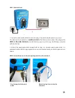
Page 17: ...when the filtration pump is on In this way the POOLeasy unit will be authorised to dose 2 Connect the power supply cable equipped with its plug in a domestic power supply socket It is preferable that...

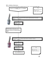
Page 18: ...n for 5 SECONDS CALIBRATING pH 7 pH 7 25 90s QUALITY 100 pH 4 0 PRESS OK RINCE PROBE PUT IN PH 4 MOVE IR AROUND STOP TOUCHING LET INSIDE pH 7 0 PRESS OK Caution before soaking the sensor in the pH 4 s...

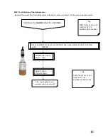
Page 19: ...THE 475 mV SOLUTION SHAKE LEAVE INSIDE WITHOUT TOUCHING pH 8 5 PRESS OK Hold down the CAL OK button for 5 SECONDS CALIBRATION mV 475 462 pH 90s QUALITY 100 475 pH PRESS OK Tip PRESS THE ESC KEY AT AN...

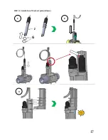
Page 20: ...17 STEP 10 Installation of the short probe 80mm G J 1 2 3...

Page 21: ...ith acid your unit is ready for use without further preparation Otherwise please refer to the following sections to adjust the advanced parameters as a function of your needs Cut Tube J to connect the...

Page 22: ...DOWN THE MENU ESC BUTTON for 5 seconds to enter the menu LANGUAGE FRENCH Language selection Once inside the menu use the and buttons to scroll between the different choices and the CAL OK button to va...

Page 23: ...ctivation time in steps of pH 0 1 for correction OVERDOSING ALARM 0 5 L 4 Hrs Setting of overdosing alarm refer to Section 5 2 4 MEASUREMENT ADJUST 0 00 pH Adjustment of the displayed value by or pH 0...

Page 24: ...3 L h OVERDOSING ALARM 0 5 L 4 Hrs Setting of overdosing alarm refer to Section 5 2 4 MEASUREMENT ADJUST 0 mV Adjustment of the displayed value by or 30 mV CAUTION improper use of this parameter may...

Page 25: ...allows dynamic monitoring of any potential overdosing HOLD DOWN THE MENU ESC KEY for 5 seconds Press CAL OK several times 4 times until you enter the OVERDOSE ALARM menu OVERDOSING ALARM 0 05 L 4 Hrs...

Page 26: ...oint desired pH To dose less the POOLeasy inserts increasingly long pauses between increasingly short operating times This is why the unit often has the pump stopped when the displayed value is not th...

Page 27: ...24 7 Maintenance 7 1 Replacement of the peristaltic tube 7 2 Maintenance of chlorine injection valve Fig 13 Clean the injector tube from chlorine deposit with acid water or replace PVC tube...

Page 28: ...s of water the measurement will deteriorate A thin layer of limescale together with other elements present in the pool water will be deposited on the sensitive elements of the sensor To mitigate this...

Page 29: ...26 7 3 2 Installation of a long probe 120mm J G P 1 2 3...

Page 30: ...g solution This allows the removal of any deposits formed during its use in pool water The sensor must be filled to 1 3 with AYACSOLSTK01 storage solution and the protective cap placed on the sensor s...

Page 31: ...mplete 2 in 1 sensor holder 9 AYFA00004 Sensor holder cap 10 AYAC100020 Strainer 11 AYAC100122 Clip 12 AYAC100010 Crystal PVC tube 4x6 13 AYAC02C001 pH4 calibration solution AYAC02C002 pH7 calibration...

Page 32: ...406 95520 OSNY France Tel 33 0 1 34 48 16 03 Fax 33 0 1 78 76 73 95 Email contact avadypool com Web www avadypool com Installation and operating instructions are included with the product when purchas...

Reviews: